
Vehicular air-conditioning system

a vehicular air conditioner and heat pump technology, applied in vehicle heating/cooling devices, heating and refrigeration combinations, vehicle machines, etc., can solve the problems of increased cooling and heating system weight, increased amount of coolant used, and insufficient coolant flow rate, etc., to achieve simple and economical structure, increase heat exchange efficiency, and good air-conditioning capability

Inactive Publication Date: 2011-07-14
HONDA MOTOR CO LTD
View PDF5 Cites 23 Cited by
  • Summary
  • Abstract
  • Description
  • Claims
  • Application Information

AI Technical Summary

Benefits of technology

[0012]It is an object of the present invention to provide a vehicular air-conditioning system which is of a simple and economical structure, allows a coolant to circulate stably, has an increased heat exchange efficiency, and is capable of maintaining a good air-conditioning capability.
[0015]According to the present invention, the coolant that remains in the condenser is retrieved to the compressor due to a pressure difference which is developed in the coolant retrieval passage connected between the condenser and the gas-liquid separator. Therefore, the coolant that remains in the condenser is retrieved easily and quickly for effectively preventing from dropping in performance.
[0017]Accordingly, it is possible for the air-conditioning system to circulate the coolant stably with a simple and economical arrangement and to operate with increased heat exchange efficiency for better air-conditioning capability.

Problems solved by technology

Therefore, cavitation (evaporation of the liquid coolant) occurs in the liquid line, tending to cause an insufficient coolant flow rate with respect to the opening of the expansion valve 4.
The receiver cycle suffers from a relatively low cooling capability.
If the cooling capability is to be increased, then the amount of coolant used and the weight of the cooling and heating system are increased, making the cooling and heating system less suitable for use on vehicles.
Furthermore, the compressor 1 needs an increase in its ability, which is detrimental to the fuel economy of the vehicle that incorporates the cooling and heating system.

Method used


Image

  • Vehicular air-conditioning system
  • Vehicular air-conditioning system
  • Vehicular air-conditioning system

Examples


Embodiment Construction

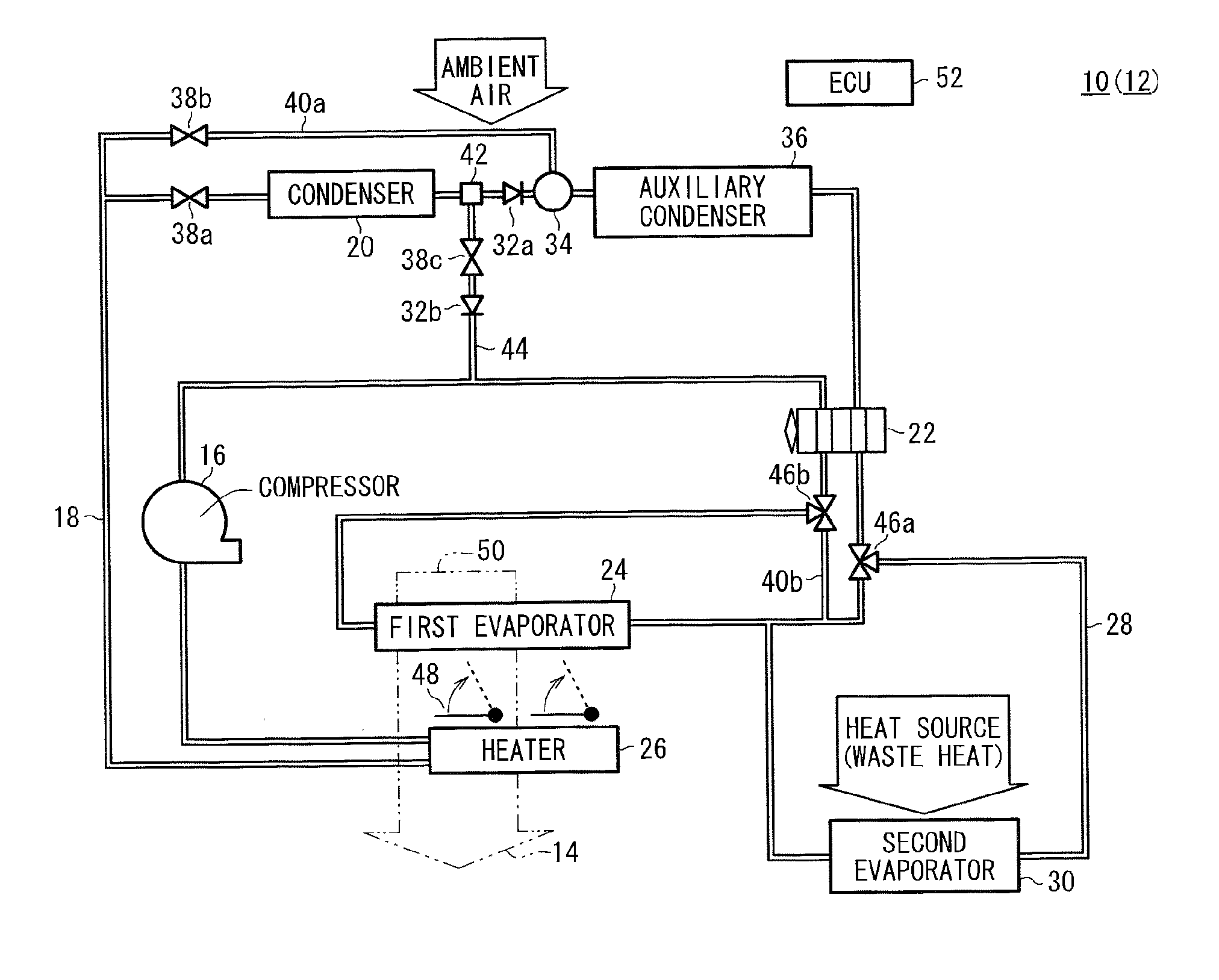
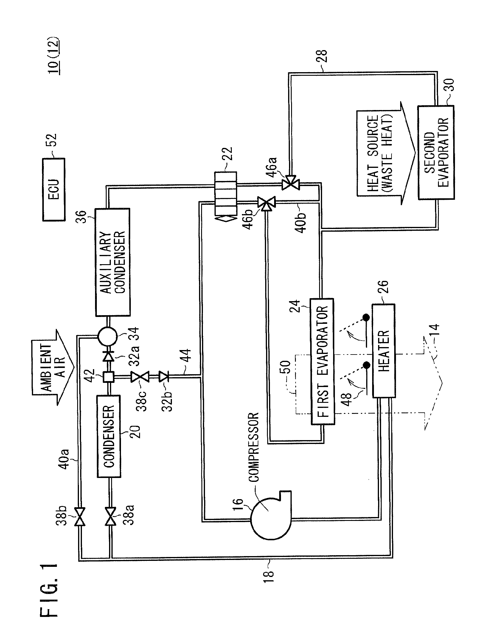
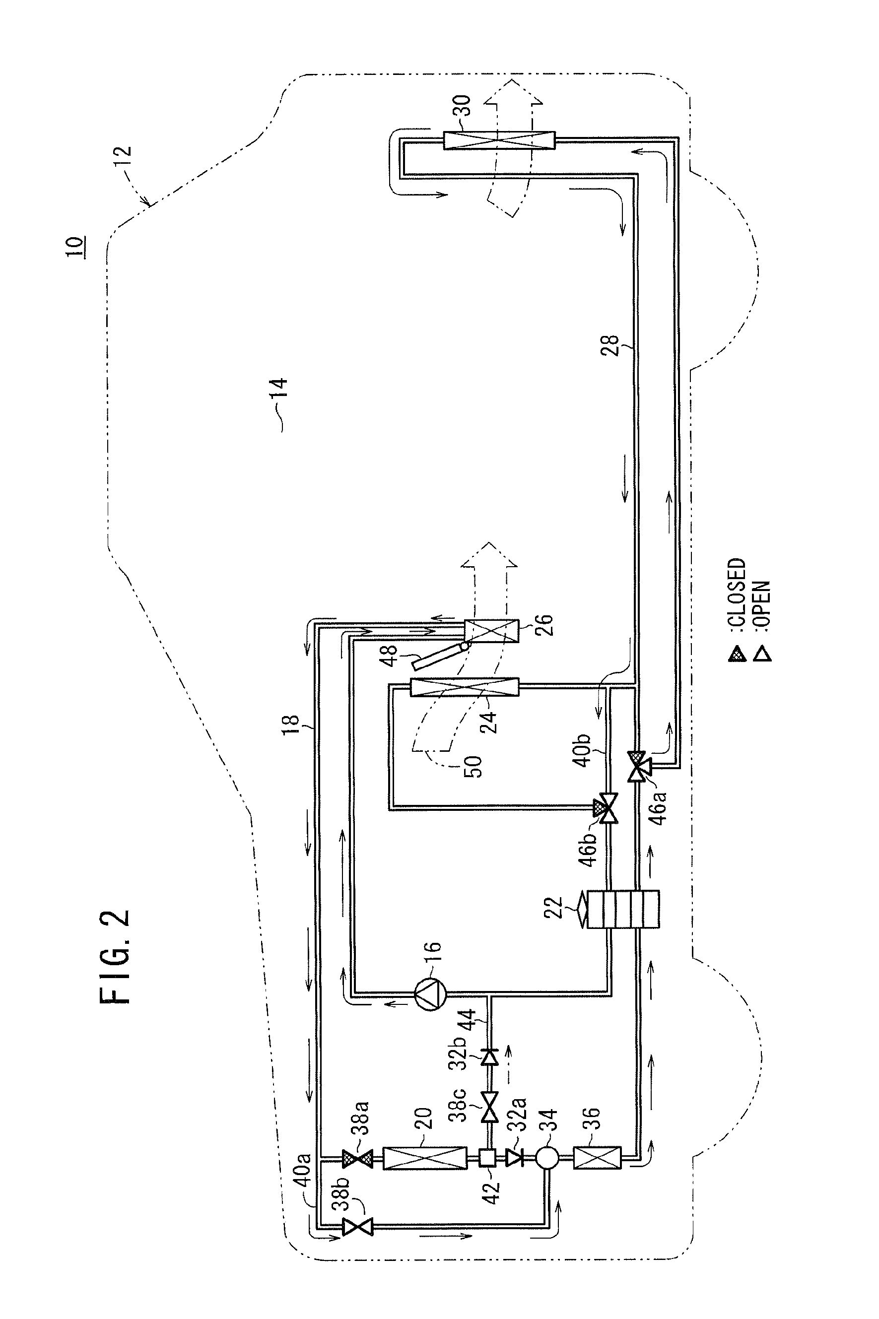
[0027]As shown in FIGS. 1 and 2, a vehicular air-conditioning system 10 according to a first embodiment of the present invention is mounted on an automobile (vehicle) 12 for air-conditioning a passenger's cabin (passenger compartment) 14 of the automobile 12.

[0028]The vehicular air-conditioning system 10 includes a heat pump circulation passage 18 through which a coolant is circulated by a compressor 16. To the heat pump circulation passage 18, there are connected a condenser 20 for performing a heat exchange between the coolant and the ambient air, an expansion valve 22 for depressurizing the coolant sent from the condenser 20, a first evaporator 24 for performing a heat exchange between the coolant that has passed through the expansion valve 22 and air-conditioning air, and a heater 26 for performing a heat exchange between the coolant which has been delivered from the compressor 16 and the air-conditioning air that has passed through the first evaporator 24.

[0029]A branch passage...


PUM


Abstract

A vehicular air-conditioning system has a heat pump circulation passage for circulating a coolant with a compressor. To the heat pump circulation passage, there are connected a condenser for performing a heat exchange between a coolant and ambient air, an expansion valve, a first evaporator, a heater, and a second evaporator. The heat pump circulation passage includes a coolant retrieval passage extending from a divider between the condenser and the gas-liquid separator and connected to the compressor. A second backflow check valve for preventing the coolant from flowing from the compressor to the divider and a solenoid-operated valve are connected to the coolant retrieval passage.

Description

CROSS-REFERENCE TO RELATED APPLICATION[0001]This application is based upon and claims the benefit of priority from Japanese Patent Application No. 2010-005117 filed on Jan. 13, 2010, of which the contents are incorporated herein by reference.BACKGROUND OF THE INVENTION[0002]1. Field of the Invention[0003]The present invention relates to a heat-pump vehicular air-conditioning system for use on a vehicle for air-conditioning the passenger's cabin of the vehicle.[0004]2. Description of the Related Art[0005]Various vehicular air-conditioning systems have been used for use on various vehicles including engine vehicle powered by an internal combustion engine, hybrid vehicles powered by an engine and a secondary battery (or a secondary battery and a fuel cell), electric vehicles, and fuel cell vehicles, etc.[0006]One of such vehicular air-conditioning systems is a heat-pump air-conditioning system. For example, as shown in FIG. 8 of the accompanying drawings, a cooling and heating system f...

Claims


Application Information

Patent Timeline
IPC IPC(8): F25B29/00F25B27/00
CPCB60H1/00914B60H2001/00949B60H1/00921B60H1/039
Inventor KOBAYASHI, SATOSHIESAKI, HIDENORIYAMAOKA, DAISUKE
Owner HONDA MOTOR CO LTD
Learn More