Automatic dual-clutch transmission

a dual-clutch transmission and automatic technology, applied in mechanical actuated clutches, transportation and packaging, gearing, etc., to achieve the effect of reducing manufacturing costs, reducing the drive power of the shift actuator, and reducing contact load

Inactive Publication Date: 2011-07-14
AISIN AI CO LTD
View PDF15 Cites 16 Cited by
  • Summary
  • Abstract
  • Description
  • Claims
  • Application Information

AI Technical Summary

Benefits of technology

[0011]With this construction, in at lease one of the low speed stage shift clutch and the reverse stage shift clutch which are simultaneously brought into engagements to establish a parking lock, the gears of the engaging member and the sleeve are able to mesh with each other at the side surfaces thereof which are formed to extend linearly in parallel to the axial direction thereof. Thus, the gear of the sleeve and the gear of the engaging member are able to mesh with each other in the circumferential direction but are prevented from meshing with each other in the axial direction. Accordingly, the drive power required for a shift actuator which moves the sleeve axially in releasing the parking lock can be reduced remarkably in comparison with the drive power required in the prior art transmission.
[0012]It is feared that because the gears of the sleeves and the engaging members are not engaged in the axial direction while being in meshing, a disengaging force exerted therebetween would generate a contact load between each sleeve and a shift fork mating therewith. However, in the present invention, the gear train in which the side surfaces of the sleeve and the engaging member are formed to extend linearly in parallel to the axial direction is set to at least one of the low speed stage gear train and the reverse stage gear train. Generally, it is for a short period of time that low speed stage gears or reverse stage gears are held in meshing during the running of the vehicle. Therefore, even if a disengaging force is exerted between the sleeve and the engaging member mating therewith, such disengaging force does not give rise to a problem because it is for a short period of time that a large contact load is imposed on the sleeve and the mating shift fork.
[0013]As described above, according to the present invention, it is possible to reduce the drive power for the shift actuator to generate at the time of releasing the parking lock, without giving rise to the problem that a contact load is exerted on the sleeve and the mating shift fork during the running of the vehicle. Further, the manufacturing cost can be reduced by forming the side surfaces on the gear of the sleeve and the side surfaces of the gear of the engaging member to surfaces which extend linearly in parallel to the axial direction. It is to be noted that the term “low speed stage gear train” means a gear train which is on the lower side than a center speed stage in a plurality of forward stages. For example, in the case of seven forward stages, the lower speed stage gear train means one of first to third speed stages.

Problems solved by technology

Therefore, even if a disengaging force is exerted between the sleeve and the engaging member mating therewith, such disengaging force does not give rise to a problem because it is for a short period of time that a large contact load is imposed on the sleeve and the mating shift fork.

Method used


Image

  • Automatic dual-clutch transmission
  • Automatic dual-clutch transmission
  • Automatic dual-clutch transmission

Examples


first embodiment

Operation of First Embodiment

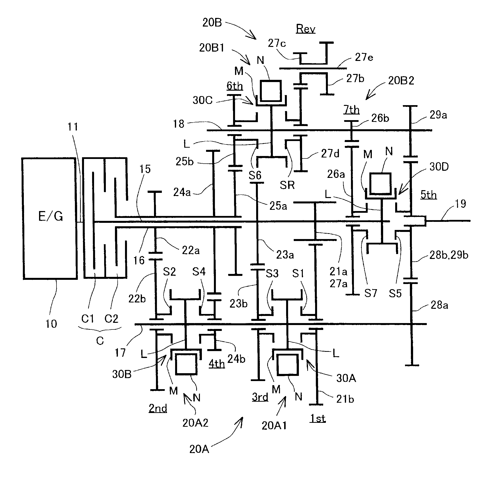
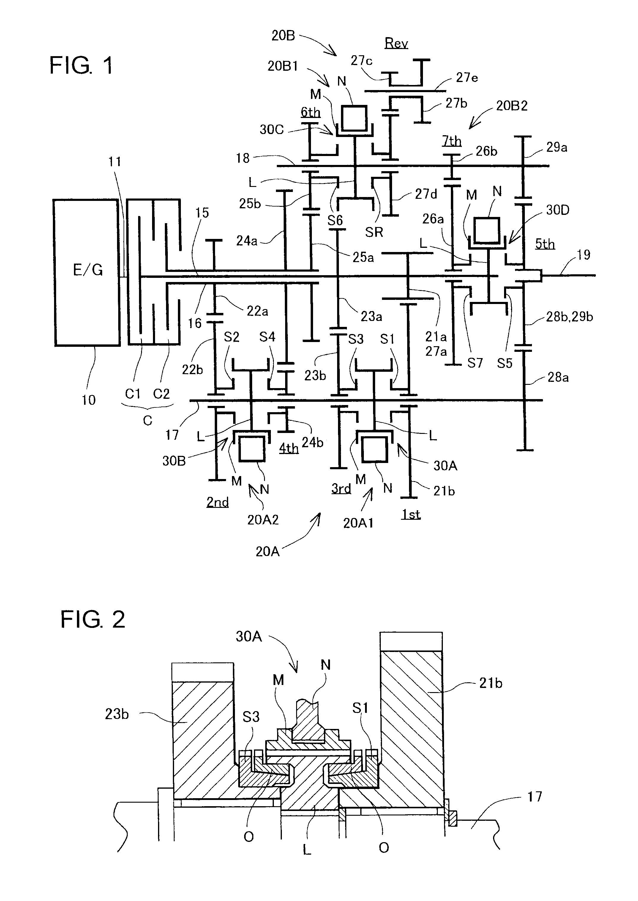
[0050]Next, the operation of the automatic dual-clutch transmission 1 in the first embodiment will be described with reference to FIG. 5. A controller (not shown) for the transmission 1 controls the first and second friction clutches C1, C2 of the dual clutch C and the first to fourth shift clutches 30A-30D to operate as indicated in FIG. 5 in dependence on the operating states of the vehicle such as throttle opening degree, engine rotational speed, vehicle speed and the like. In the state of an out-of-operation, the first and second friction clutches C1, C2 of the dual clutch C are both released, and each of the first to fourth shift clutches 30A-30D is in the neutral position.

[0051]Even when the engine 10 is started with the vehicle remaining stopped, the same state as the aforementioned state of the out-of-operation is maintained. When a shift lever (not shown) of the dual-clutch gear transmission 1 is set to a forward position after the engine 10 is ...

second embodiment

Operation of Second Embodiment

[0089]Next, the operation of the automatic dual-clutch transmission 100 in the second embodiment will be described with reference to FIG. 8. A controller (not shown) for the transmission 100 controls the first and second friction clutches C1, C2 of the dual clutch C and the first to fourth shift clutches 130A-130D to operate as indicated in FIG. 8 in dependence on the operating states of the vehicle such as throttle opening degree, engine rotational speed, vehicle speed and the like. In the state of an out-of-operation, the first and second friction clutches C1, C2 of the dual clutch C are both released, and each of the first to fourth shift clutches 130A-130D is in the neutral position.

[0090]When the engine 10 is operated with the vehicle remaining stopped, the same state as the aforementioned state of the out-of-operation is maintained. When a shift lever (not shown) of the dual-clutch gear transmission 100 is set to a forward position after the engin...


PUM


Abstract

An automatic dual-clutch transmission is able to establish a parking lock by bringing one of a first input shaft and a second input shaft into engagements with a low speed stage gear train as well as with a reverse stage gear train in performing a parking. Gears of an engaging member and a mating sleeve in at least one of a low speed stage shift clutch and a reverse stage shift clutch which are simultaneously brought into engagements to establish the parking lock are able to mesh with each other at axially extending side surfaces thereof which are formed to extend linearly in parallel to an axial direction thereof.

Description

INCORPORATION BY REFERENCE[0001]This application is based on and claims priority under 35 U.S.C. 119 with respect to Japanese patent application No. 2010-005764 filed on Jan. 14, 2010, the entire content of which is incorporated herein by reference.BACKGROUND OF THE INVENTION[0002]1. Field of the Invention[0003]The present invention relates to an automatic dual-clutch transmission having a dual clutch which is capable of transmitting the rotational drive power from a prime mover to two input shafts. Particularly, it relates to an automatic dual-clutch transmission with a parking lock function.[0004]2. Discussion of the Related Art[0005]Heretofore, there has been known an automatic dual-clutch transmission described in US2007 / 0289399 A1 (equivalent of JP2007-331654 A: hereafter referred to as “Patent Document 1”). This patent document describes performing a parking lock in parking a vehicle. The known transmission incorporates a plurality of engaging members which mate with respectiv...

Claims


Application Information

Patent Timeline
Patent Type & Authority Applications(United States)
IPC IPC(8): F16H37/06
CPCF16D23/06F16D2023/0656F16D2023/0668F16H3/006Y10T74/1907F16H61/0059F16H63/48F16H2200/0056F16H3/097
Inventor KATO, HIROYUKIOGAMI, SHIRO
Owner AISIN AI CO LTD
Why Eureka
Try Eureka