

Stator for an electric machine
a technology of electric machines and statators, applied in the field of electric machines, can solve the problems of mechanical oscillations that cannot be easily filtered, vehicle vibration and noise, motor torque output speed oscillations, etc., and achieve the effect of reducing the magnitude of torque ripple and substantially constant average torque of electric machines
- Summary
- Abstract
- Description
- Claims
- Application Information
AI Technical Summary
Benefits of technology
Problems solved by technology
Method used
Image

Examples
Embodiment Construction
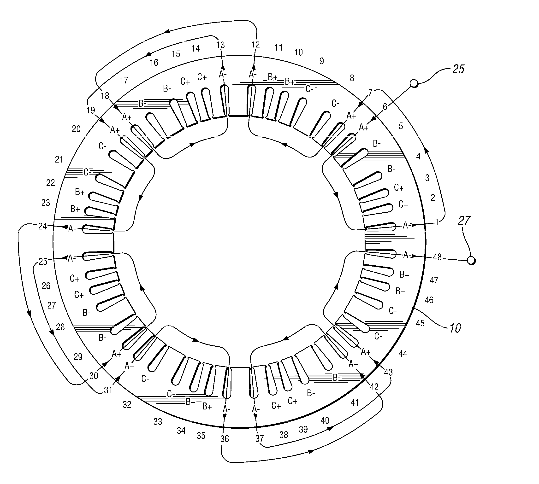
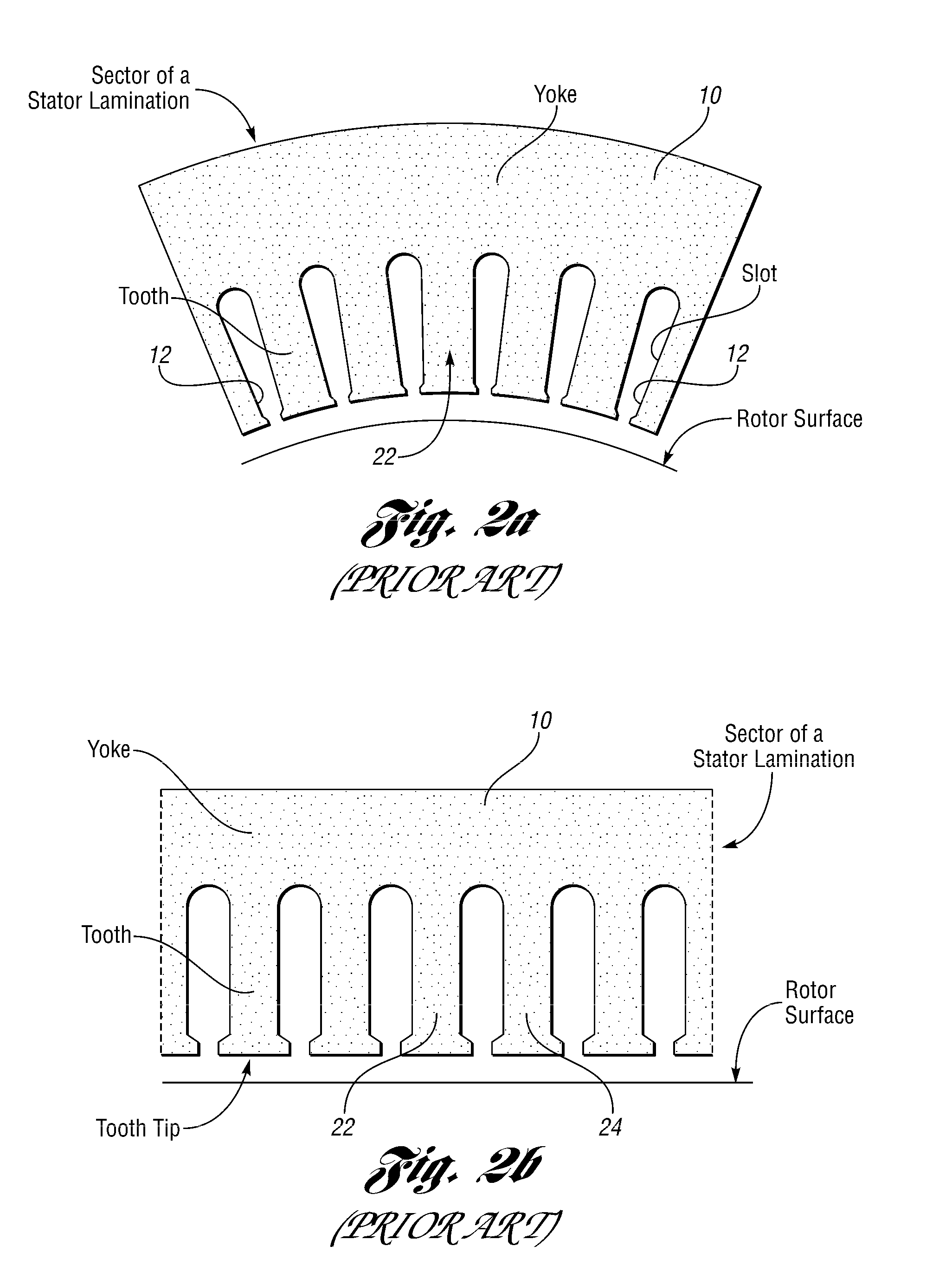
[0011]The electric machine of the present invention has stator laminations with irregular teeth. It is capable of reducing the magnitude of the torque ripple previously described while maintaining the average torque of the electric machine substantially constant when compared to a conventional stator with regular tooth geometry for the laminations. The stator lamination design of the present invention can be used in any type of electric machine, although embodiments presently disclosed include an interior permanent magnet machine.
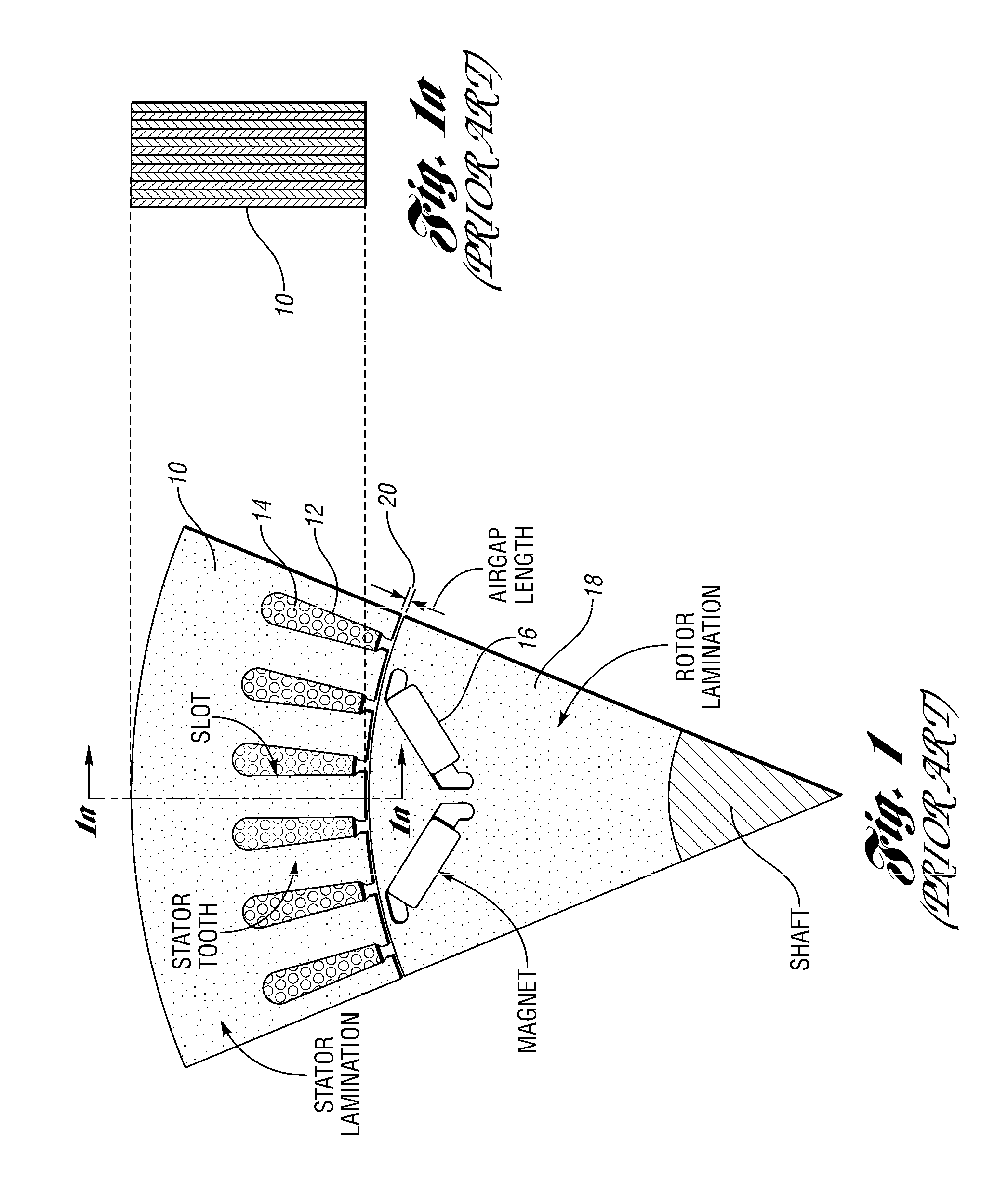
[0012]The teeth of the stator laminations are located along the inner diameter of the laminations. The invention modifies the effect of variations of the air-gap permeance while maintaining a consistent average value of the air gap permeance to reduce harmonic fluxes that lead to a reduction of a targeted torque ripple, particularly the 24th order torque ripple.
[0013]According to one embodiment of the invention, an irregular tooth geometry is achieved by fo...
PUM
 Abstract
Description
Claims
Application Information