Liquid crystal display device

a display device and liquid crystal technology, applied in the field of liquid crystal display devices, can solve the problems of increasing the number of device components, increasing the cost, and not being able to achieve good specific effects

Inactive Publication Date: 2011-07-14
SONY CORP
View PDF5 Cites 3 Cited by
  • Summary
  • Abstract
  • Description
  • Claims
  • Application Information

AI Technical Summary

Benefits of technology

[0048]Described next are the effects and advantages of the liquid crystal display device 1 in this embodiment.
[0049]With this liquid crystal display device 1, as illustrated in FIG. 1, first of all, the image processing section 41 performs the above-described predetermined image processing on an input video signal Din, thereby generating a video signal as a result of the image processing. This resulting video signal after the image processing is supplied to the data driver 51 through the timing control section 42. The data driver 51 then applies D/A conversion to the resulting video signal after the image processing so that a video voltage being an analog signal is generated. The gate driver 52 and the data driver 51 each output a drive voltage to each of the pixels 20 so that the operation for display driving is accordingly performed.
[0050]To be specific, as illustrated in FIG. 2, the TFT elements 21 are turned ON and OFF in accordance with a selection signal provided by the gate driver 52 over the gate lines G. This accordingly allows conduction of electricity selectively between the data lines D and the liquid crystal elements 22, and between the data lines D and the auxiliary capacity elements 23. As a result, the video voltage coming from the data driver 51 is directed to the liquid crystal elements 22, thereby leading to the operation for line-sequential display driving, i.e., drive operation for line-sequential writing.
[0051]On the other hand, in the backlight drive section 50, as illustrated in FIG. 3, the upper and lower inverte

Problems solved by technology

In such techniques of Japanese Unexamined Patent Publication No. 2000-321993 and No. 2000-321551, the blinking operation may solve the blurring problem of moving images, however, the resulting effects are not good enough specifically in the border region between any two of the divided emission regions because the light each coming therefrom is to be mixed in the border region.
This thus increases the number of device components, thereby resulting in a cost increase.
Also with the technique in Japanese

Method used


Image

  • Liquid crystal display device
  • Liquid crystal display device
  • Liquid crystal display device

Examples


embodiment

(Entire Configuration of Liquid Crystal Display Device)

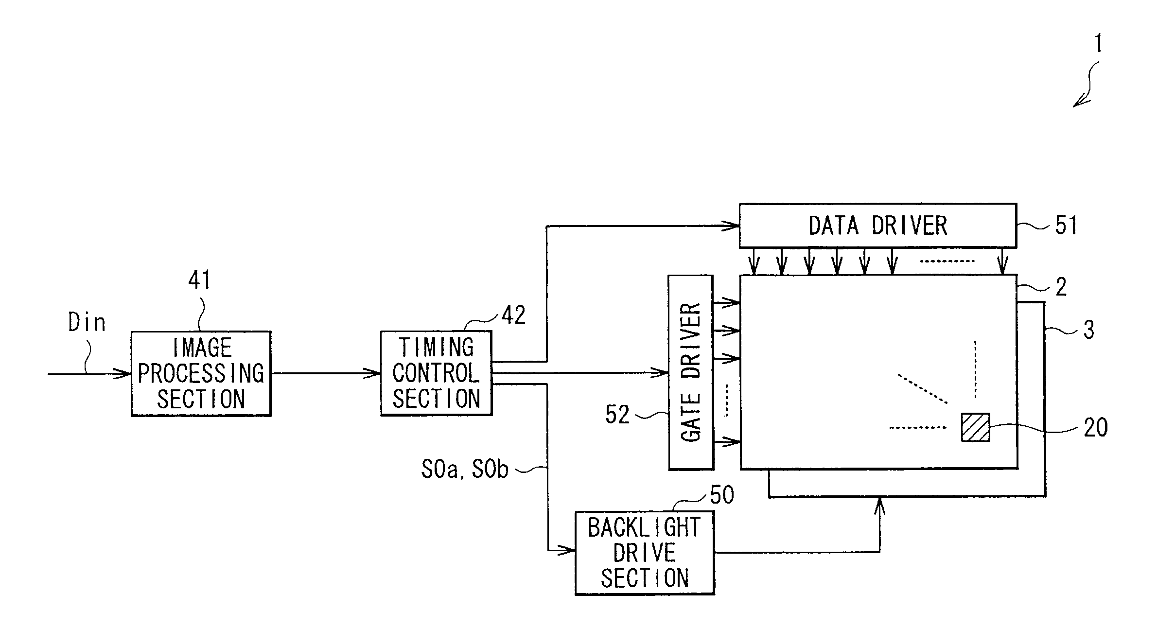
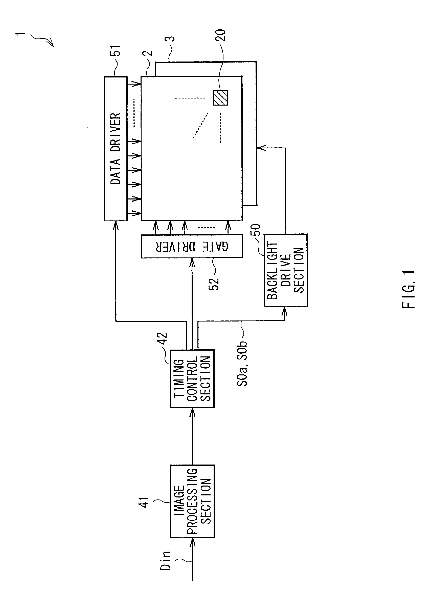
[0031]FIG. 1 is a block diagram showing the configuration of a liquid crystal display device, i.e., liquid crystal display device 1, in the embodiment of the invention. The liquid crystal display device 1 is of a so-called transmissive type, and is configured to include a backlight 3 (light source section), and a transmissive liquid crystal display panel 2. This liquid crystal display device 1 is also provided with an image processing section 41, a timing control section 42, a backlight drive section 50, a data driver 51, and a gate driver 52. Among these device components, the timing control section 42, the backlight drive section 50, the data driver 51, and the gate driver 52 are all a specific example of a “drive section” in the embodiment of the invention.

[0032]The backlight 3 is a light source from which a light is directed toward the liquid crystal display panel 2. In this example, the backlight 3 is of a direct-light type...

modified example

[0073]Described next is a modified example of the embodiment described above. Herein, any device component same as that in the above embodiment is provided with the same reference numeral, and is not described again if appropriate.

[0074]FIG. 12A is a schematic diagram showing the configuration of a backlight, i.e., backlight 3A, in the modified example, and FIG. 12B is a timing chart of the turn-ON operation (control operation) of this backlight 3A.

[0075]As illustrated in FIG. 12A, the backlight 3A of this modified example is configured to include a light guide plate 33A, and LEDs 31A and 31B different in type. The light guide plate 33A forms the whole emission region 30. To be specific, the LED 31A (upper light source) is disposed along the edge of the light guide plate 33A on the side of the upper emission region 301, and the LED 32A (lower light source) is disposed along the edge of the light guide plate 33A on the side of the lower emission region 302. In other words, this backl...


PUM


Abstract

A liquid crystal display device includes: a light source section; a liquid crystal display panel including pixels and performing video display; and a drive section. The drive section performs the driving on the light source section for turning ON and OFF in synchronization with the driving of the pixels for the light-sequential writing such that, the liquid crystal display panel is selectively illuminated with the light from a lower emission region in the light source section when the pixels in an upper display region are under the driving for line-sequential writing, and such that, the liquid crystal display panel is selectively illuminated with the light from an upper emission region when the pixels in a lower display region are under the driving for line-sequential writing. A phase difference between emission periods in the upper and lower emission regions falls within a range from 90° to 150° both inclusive.

Description

BACKGROUND OF THE INVENTION[0001]1. Field of the Invention[0002]The present invention relates to a liquid crystal display device performing video display through division of an emission region in a light source device such as backlight.[0003]2. Description of the Related Art[0004]In recent years, a demand for thinner displays has been growing especially for liquid crystal televisions and PDPs (Plasma Display Panels). Displays for mobile use are often liquid crystal displays, and are especially expected to be high in reproducibility of color with good fidelity.[0005]In a liquid crystal display device, liquid crystal elements are generally subjected to an operation of line-sequential driving, i.e., operation of line-sequential writing, in the vertical direction from an upper to lower end on the display screen. The liquid crystal elements are those respectively provided in a plurality of pixels arranged in a matrix. At the frame frequency of about 30 to 240 Hz, a frame is generally pro...

Claims


Application Information

Patent Timeline
IPC IPC(8): G09G3/36G06F3/038
CPCG09G3/342G09G2320/064G09G2320/0257G09G2310/024
Inventor KIKUCHI, NORIFUMIOGAWA, SHINJIYOSHIZAWA, YORIAKI
Owner SONY CORP
Why Eureka
Try Eureka