
Fiber laser oscillators and systems using an optimized phase varying function

a fiber laser and phase varying technology, applied in the field of pulsed fiber lasers, can solve the problems of limiting the possible amplification of signals, stokes wave can possibly be destructive for upstream optical components, and the operation of a mopa system based on active optical fibers is limited

Inactive Publication Date: 2011-07-14
INSTITUT NATIONAL D'OPTIQUE
View PDF6 Cites 15 Cited by
  • Summary
  • Abstract
  • Description
  • Claims
  • Application Information

AI Technical Summary

Benefits of technology

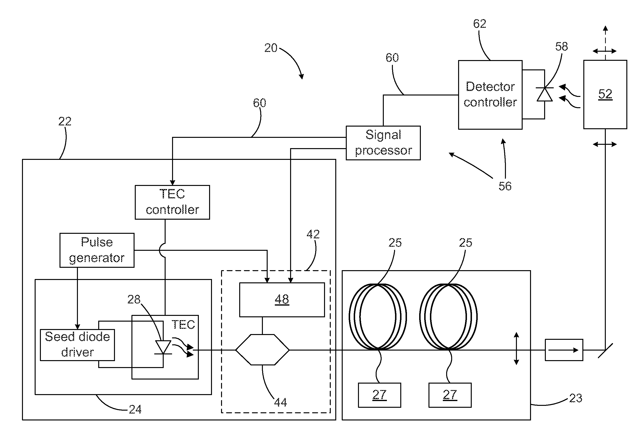
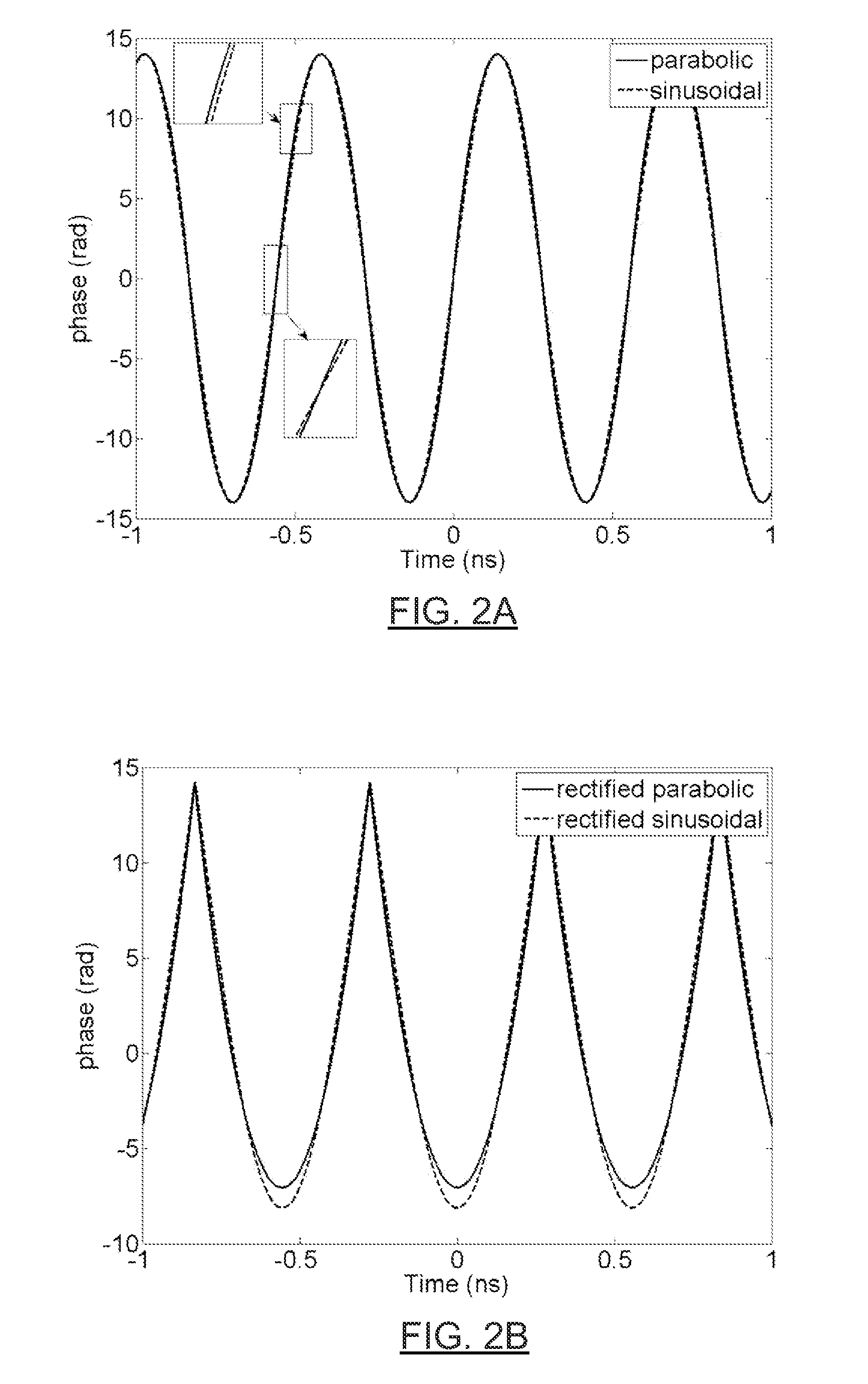
The present invention provides a pulsed fiber laser oscillator and a laser system that can tailor the spectral profile of optical pulses to achieve a desired peak spectral density and spectral width. The spectral tailoring module imposes a phase variation on each optical pulse according to an optimized phase varying function, which can have a rectified sinusoidal shape, a parabolic shape, or a rectified parabolic shape. The laser system also includes a fiber power amplifier module for amplifying the optical pulses. The technical effects of the invention include improved laser pulse quality, improved laser system efficiency, and improved laser system stability.

Problems solved by technology

However, pulsed operation of a MOPA system based on active optical fibers is limited by the onset of nonlinear effects.
This limits the possible amplification of the signal and the Stokes wave can possibly be destructive for upstream optical components.
This certainly limits the effective area of the doped fiber that can be used since high-order modes in multimode optical fibers degrade the achievable beam quality factor (M2), induce astigmatism, induce asymmetry and affect the beam pointing stability (see S. Wielandy “Implications of higher-order mode content in large mode area fibers with good beam quality” Opt.
A laser signal with a broad spectral content, that is, larger than the acceptance bandwidth of the crystal, will not be efficiently frequency converted.
However, spectral filtering with a wavelength selective element of a phase-modulated source can have a detrimental effect on its temporal amplitude stability.
Phase modulated signals may also suffer from reduced harmonic conversion efficiency.

Method used


Image

  • Fiber laser oscillators and systems using an optimized phase varying function
  • Fiber laser oscillators and systems using an optimized phase varying function
  • Fiber laser oscillators and systems using an optimized phase varying function

Examples


Embodiment Construction

[0029]Embodiments of the present invention generally provide pulse generating methods, pulsed fiber laser oscillators and laser systems adapted for high power applications such as memory repair, milling, micro-fabrication, drilling and other material processing applications. In some embodiments, such laser systems may be particularly useful where spectral filtering, frequency conversion and / or amplification of the output beam is desired. It will however be understood that embodiments of the present invention may also be used in other contexts such as remote sensing or any other application which may benefit from high power pulses having good optical characteristics.

Pulsed Fiber Laser Oscillator

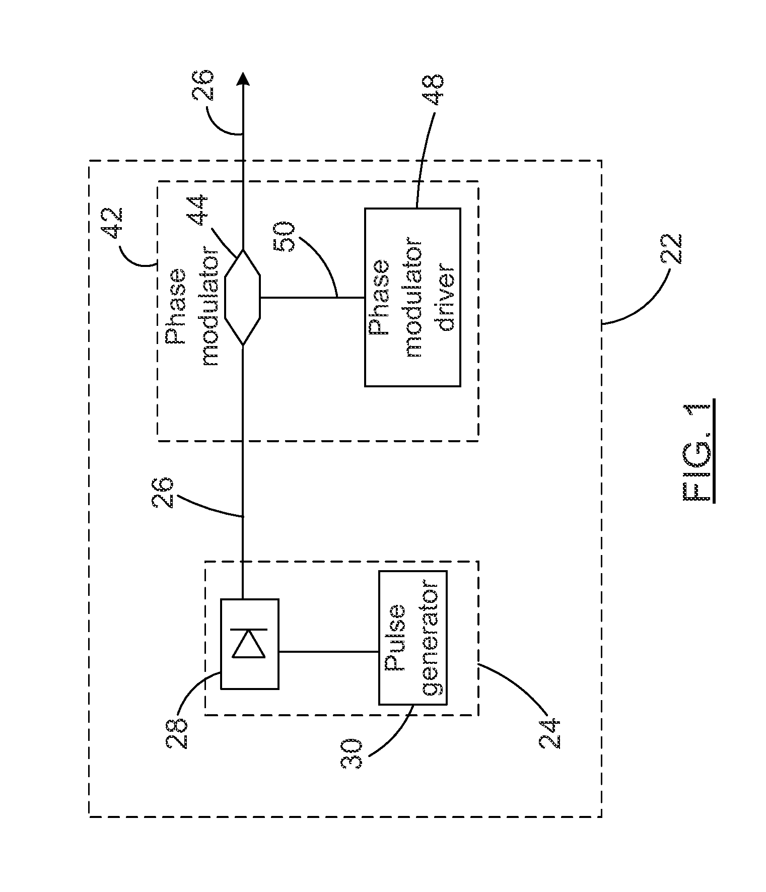
[0030]Referring to FIG. 1, there is shown a pulsed fiber laser oscillator 22 according to one embodiment of the invention.

[0031]The expression “oscillator” is understood to refer to the portion of a laser system that generates optical pulses. The expression “optical pulses” or “light pulses” i...


PUM


Abstract

A pulsed fiber laser oscillator and laser systems incorporating such laser oscillators are presented. The laser oscillator first includes a light generating module which generates optical pulses having an initial spectral profile. A spectrum tailoring module tailors the initial spectral profile of the optical pulses by imposing a phase variation on each optical pulse according to an optimized phase varying function. The optimized phase varying function has one of a rectified sinusoidal shape, a parabolic shape and a rectified parabolic shape. Laser systems incorporating such oscillators may be of a MOPA configuration, and may further include a nonlinear crystal for frequency conversion or a bulk solid-state amplifier.

Description

[0001]This application claims benefit of Ser. No. 61 / 288,784, filed 21 Dec. 2009 in the United States and which application is incorporated herein by reference. To the extent appropriate, a claim of priority is made to each of the above disclosed applications.FIELD OF THE INVENTION[0002]The present invention relates to the field of pulsed fiber lasers and more particularly concerns methods and systems tailoring the spectral profile of optical pulses using an optimized phase varying function to improve beam quality.BACKGROUND[0003]Active optical fiber is the gain medium of choice for high power applications, as it is both efficient and robust. Such fibers are particularly useful in a Master Oscillator Power Amplifier (MOPA) architecture, which provides a versatile pulse generation scheme. However, pulsed operation of a MOPA system based on active optical fibers is limited by the onset of nonlinear effects. Those effects result from the guided propagation of high-peak power signals ov...

Claims


Application Information

Patent Timeline
Patent Type & Authority Applications(United States)
IPC IPC(8): H01S3/30
CPCH01S3/0085H01S3/0092H01S3/067H01S3/2308H01S3/1024H01S3/1305H01S3/06754
Inventor DESBIENS, LOUISROY, VINCENTDELADURANTAYE, PASCALSISTO, MARCO MICHELETAILLON, YVESBAIRD, BRIAN W.
Owner INSTITUT NATIONAL D'OPTIQUE
Learn More