
Radiographic image capturing system

a technology of radiographic images and capturing systems, applied in the field of radiographic image capturing systems, can solve the problems of difficult synchronization and inability to capture fluoroscopic images reliably, and achieve the effect of reducing the amount of illumination radiation per unit time and excellent images

Active Publication Date: 2011-07-14
FUJIFILM CORP
View PDF2 Cites 21 Cited by
  • Summary
  • Abstract
  • Description
  • Claims
  • Application Information

AI Technical Summary

Benefits of technology

[0019]Thus, exposure of a subject when radiation is being continuously irradiated may be restrained.
[0020]In the present aspect, the radiographic image capture device may includes a radiographic detector in which a plurality of pixels that generate charges when radiation is irradiated thereon and store the charges are arranged in two dimensions, the radiographic detector outputting the charges stored in the pixels as electronic signals; amplifiers that amplify the electronic signals output by the radiographic detector; and an image capture device controller that, in case in which the continuous irradiation is performed, performs at least one of: extending a storage period of the charges at the pixels to be longer than in the pulse irradiation; increasing a gain amount of the amplifiers to be higher than in the pulse irradiation; or image processing that combines a plurality of adjacent pixels as a single pixel.

Problems solved by technology

However, with pulse irradiation, there is the need to synchronize the timing of irradiating the radiation from the radiation source and the timing of the image capturing at the radiation detector.
However, if transmitting and synchronizing beacon signals by radio communication to synchronize irradiation timings with image capture timings is attempted, the synchronization is difficult because of communication delays and the like, and fluoroscopic images may not be captured reliably.

Method used


Image

  • Radiographic image capturing system
  • Radiographic image capturing system
  • Radiographic image capturing system

Examples


first exemplary embodiment

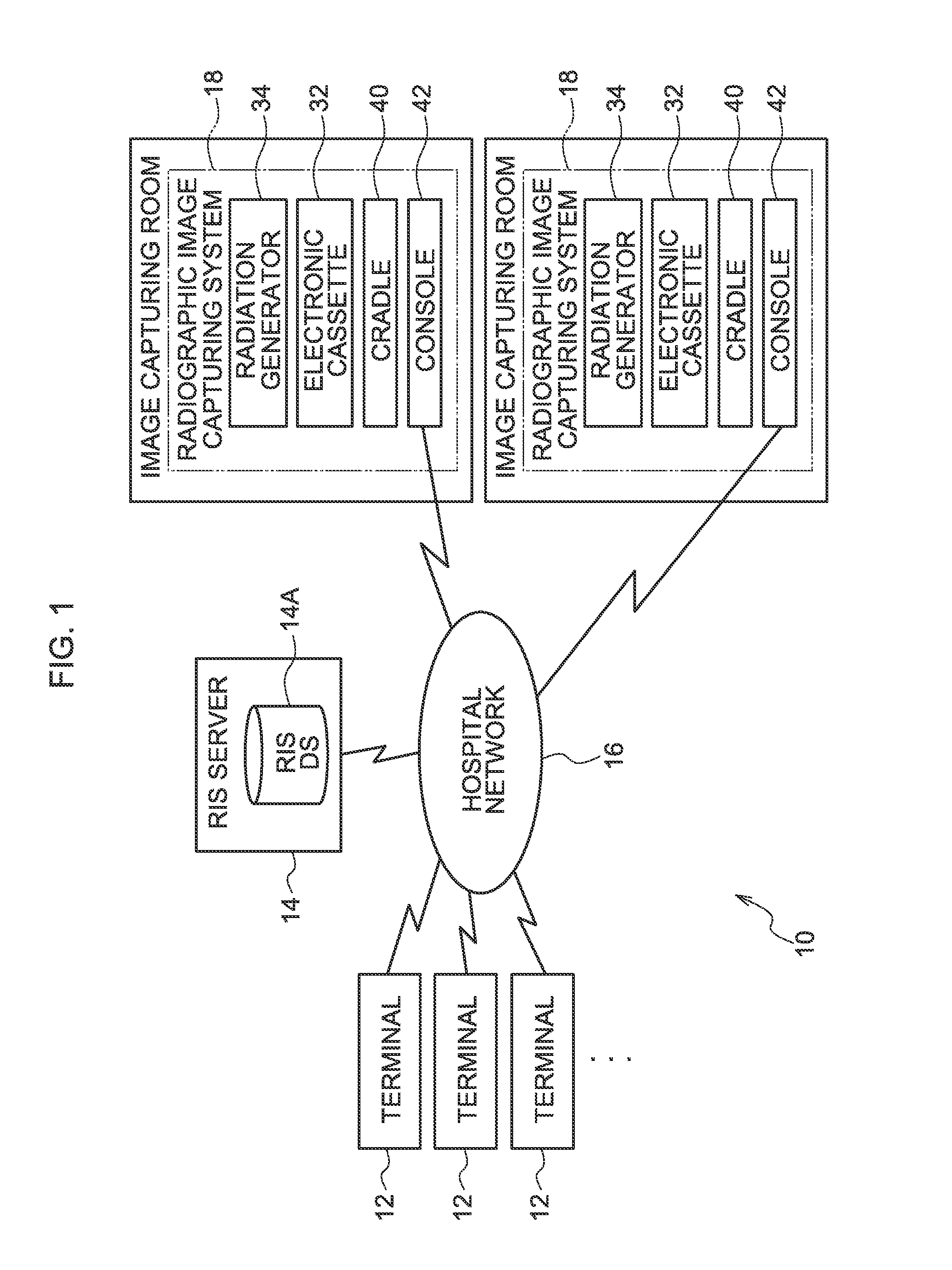
[0048]A configuration of a radiology information system 10 (which will be called “the RIS 10” below) of the present embodiment will be described in reference to FIG. 1.

[0049]The RIS 10 is a system for managing information such as medical service appointments and diagnostic records in a radiology department and configures part of a hospital information system (HIS).

[0050]The RIS 10 includes plural image capture request terminals 12 (which will be called “the terminals 12” below), a RIS server 14 and radiographic image capturing systems 18 (hereinafter, referred to as “capturing systems”) installed in individual radiographic image capturing rooms (or operating rooms) in a hospital being connected to a hospital network 16 that is structured by a wired or wireless local area network (LAN). The RIS 10 serves as part of the HIS that is disposed in the same hospital, and an HIS server (not shown) that manages the entire HIS is also connected to the hospital network 16.

[0051]The terminals 1...

second exemplary embodiment

[0145]The image capturing system 18 relating to the second exemplary embodiment is capable of radio communication between the console 42 and the radiation generator 34.

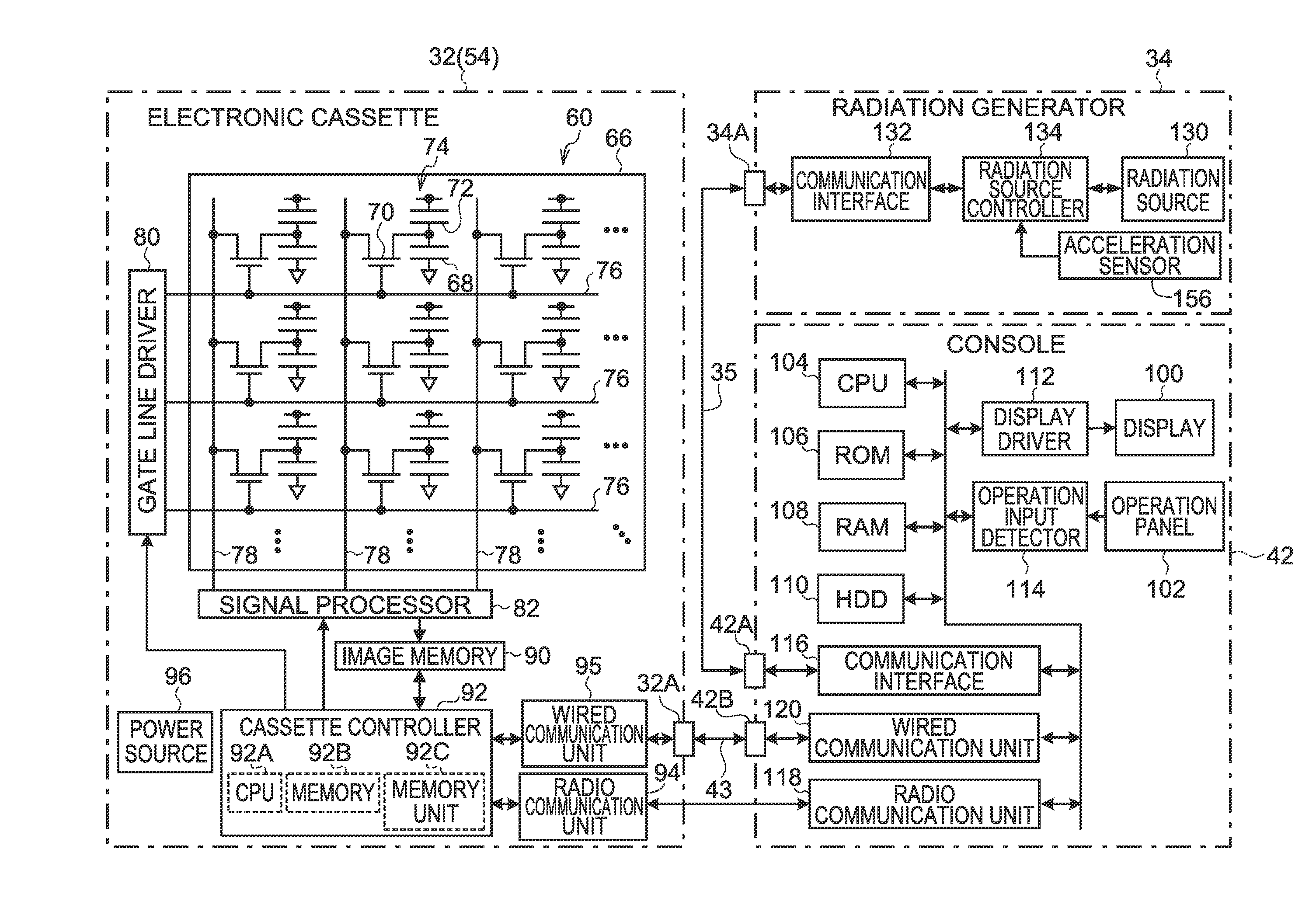
[0146]FIG. 13 shows a block diagram illustrating a configuration of principal elements of an electronic system of the image capturing system 18 relating to the second exemplary embodiment. Portions that are the same as in the image capturing system 18 of the first exemplary embodiment (see FIG. 4) are assigned the same reference numerals and will not be described.

[0147]The radiation generator 34 relating to the present exemplary embodiment is additionally provided with a radio communication unit 135 that sends and receives various kinds of information (data) by radio communication.

[0148]If the radiation generator 34 and console 42 relating to the present exemplary embodiment are connected by the communication cable 35, wired communication is performed and if the same are not connected by the communication cable 35, ra...

third exemplary embodiment

[0155]The image capturing system 18 relating to the third exemplary embodiment is not equipped with the console 42, but various kinds of instruction operation relating to imaging may be performed at the electronic cassette 32.

[0156]FIG. 15 illustrates a configuration of principal elements of an electronic system of an imaging system relating to the third exemplary embodiment. Portions that are the same as in the image capturing system 18 of the first exemplary embodiment (see FIG. 4) are assigned the same reference numerals and descriptions thereof are omitted.

[0157]The radiation generator 34 relating to the present exemplary embodiment is provided with an operation panel 97 for various instruction operations relating to image capture by the electronic cassette 32 and with a display unit 98 for displaying various kinds of information. In the present exemplary embodiment, the operation panel 97 of the electronic cassette 32 may implement designation of the image capture mode, designa...


PUM


Abstract

A radiographic image capturing system includes a radiographic image capture device, a radiation irradiation device, and a control device. The radiographic image capture device is capable of wired and wireless communications, and is capable of fluoroscopic imaging in which radiographic images are successively captured at notified synchronization timings or at a predetermined frame rate. The radiation irradiation device irradiates radiation toward the radiographic image capture device during fluoroscopic imaging, with continuous irradiation or pulse irradiation. The control device includes a wireless communication unit, a wired communication unit, and a controller that, if communication with the radiographic image capture device is performed by the wireless communication unit, prohibits fluoroscopic imaging with pulse irradiation in which the synchronization timings are notified to the radiographic image capture device and radiation is irradiated from the radiation irradiation device in pulses matching the notified synchronization timings.

Description

CROSS-REFERENCE TO RELATED APPLICATION[0001]This application claims priority under 35 USC 119 from Japanese Patent Application No. 2010-003256 filed on Jan. 8, 2010, the disclosure of which is incorporated by reference herein.BACKGROUND OF THE INVENTION[0002]1. Field of the Invention[0003]The present invention relates to a radiographic image capturing system, and in particular, to a radiographic image capturing system that is capable of wired communication using a communication cable and wireless communication, and can carry out fluoroscopic imaging in which the capturing of radiographic images is carried out continuously at notified synchronization timings or at a predetermined frame rate.[0004]2. Description of the Related Art[0005]Radiation detectors such as flat panel detectors (FPDs), in which a radiation-sensitive layer is disposed on a thin film transistor (TFT) active matrix substrate and that can convert radiation directly into digital data have been put into practice in re...

Claims


Application Information

Patent Timeline
Patent Type & Authority Applications(United States)
IPC IPC(8): H05G1/56
CPCA61B6/102A61B6/4283A61B6/4405A61B6/4441A61B6/487A61B6/548A61B6/542A61B6/545A61B6/56A61B6/586A61B6/4423A61B6/54
Inventor NAKATSUGAWA, HARUYASUIWAKIRI, NAOTONISHINO, NAOYUKIOHTA, YASUNORIYOSHIDA, YUTAKA
Owner FUJIFILM CORP
Learn More