On hold call back telephone feature

a telephone feature and call back technology, applied in the field of telephones, can solve problems such as significant connect-time charges

Inactive Publication Date: 2011-07-14
PHONE FEATURES +1
View PDF13 Cites 40 Cited by
  • Summary
  • Abstract
  • Description
  • Claims
  • Application Information

AI Technical Summary

Benefits of technology

[0038]FIG. 12 is a schematic diagram of circuitry implementing the second embodiment of the present inventio

Problems solved by technology

In conventional telephony systems, one party placed on hold by the other party upon initial connection, such as when a receiver of a telephone call places the caller on hold, the party placed on hold must simply wait for t

Method used


Image

  • On hold call back telephone feature
  • On hold call back telephone feature
  • On hold call back telephone feature

Examples


first embodiment

[0061]When implementing the present invention in conjunction with a Telephone Central Office, the Callback on Hold feature can be implemented on any stored-program control (SPC) central office telephone switch, which handle virtually all land-based phone lines in the United States. Most of these are all-digital exchanges, first deployed in the 1980's in which the analog voice signals are digitized at the incoming calling subscriber's line card, passed through a time-space-time (T-S-T) network, and converted back to analog at the called subscriber's line card. Examples of such exchanges are the No. 5 ESS, originally manufactured by Western Electric and now by Alcatel-Lucent; the DMS-100, originally manufactured by Northern Telecom, now Nortel; and the GTD-5 EAX, originally manufactured by GTE Automatic Electric and now also sold by Alcatel-Lucent.

[0062]Since the call processing functions of such a switch are entirely handled in software, the “Callback on Hold” feature can be implemen...

second embodiment

[0091]FIGS. 5-12 illustrate the invention, capable of performing “on-hold call back” without any required cooperation from a central office switch, implemented in a variety of consumer electronic devices, including cellular telephones, electronic land-line telephones, stand-alone answering machines, answering machines with integrated telephone sets, and cordless telephone answering systems.

[0092]Referring to FIG. 5, the second embodiment of the present invention is implemented using, in part, embedded microprocessor-based software or firmware additions to a conventional cellular telephone. As shown in FIG. 5, the major components of a standard cellular telephone include a Digital Baseband 201 which includes the microcontroller (MCU) and Digital Signal Processor (DSP); Analog Baseband 202 which includes Analog to Digital (A / D) and Digital to Analog (D / A) converters; Speaker 203; Handset microphone 204; Flash memory 205; RF Transceiver and Power Amplifier (PA) 206 connected to the ant...


PUM


Abstract

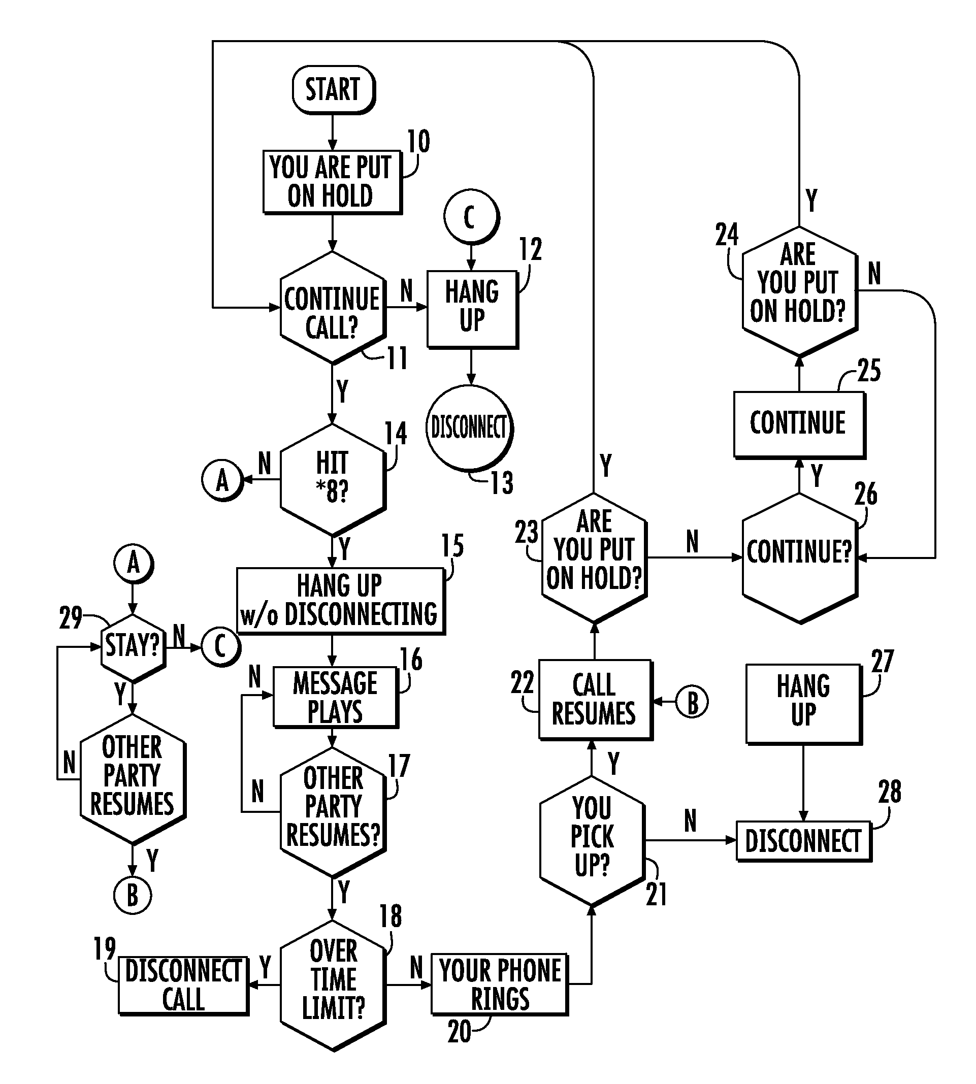
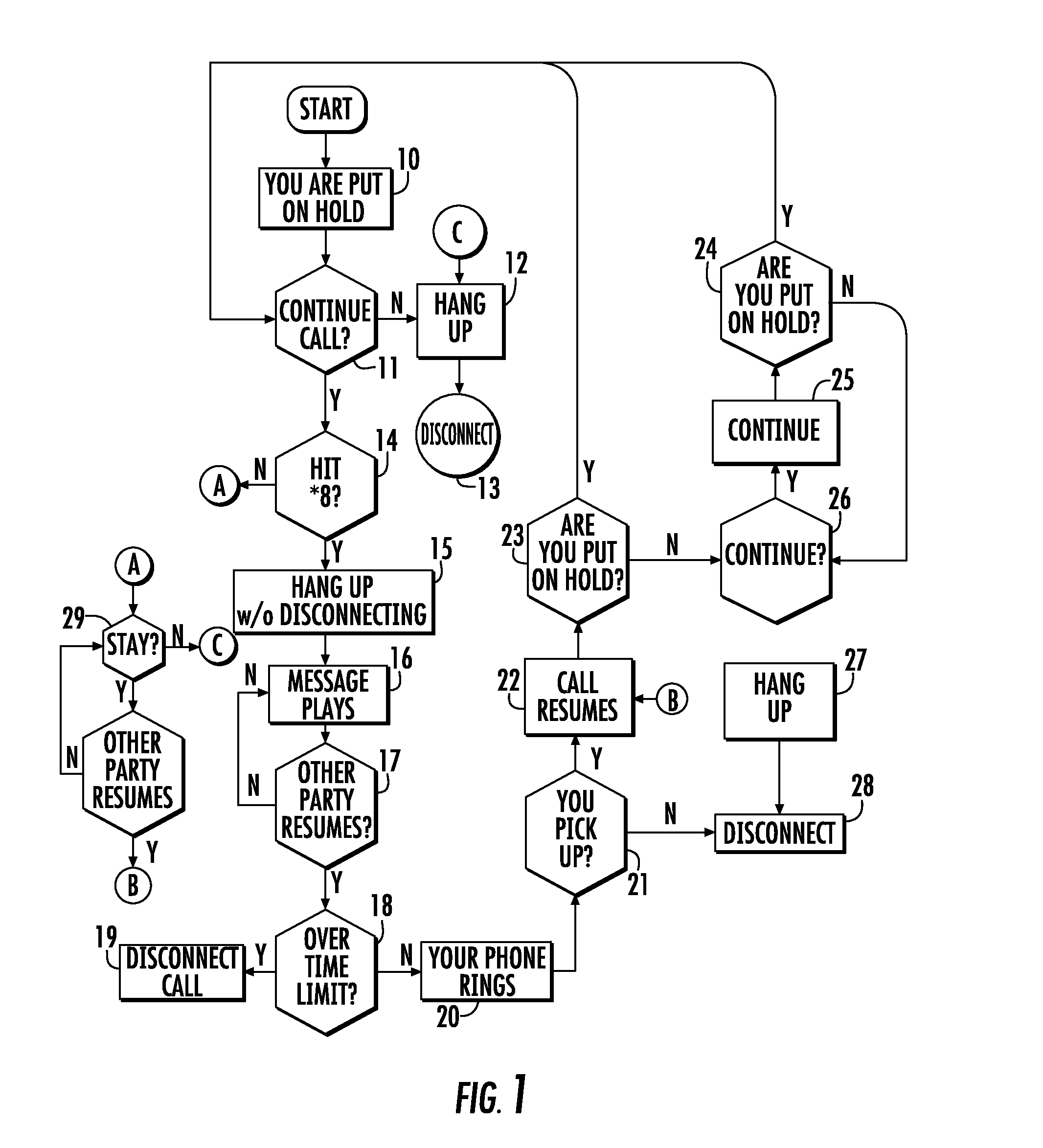
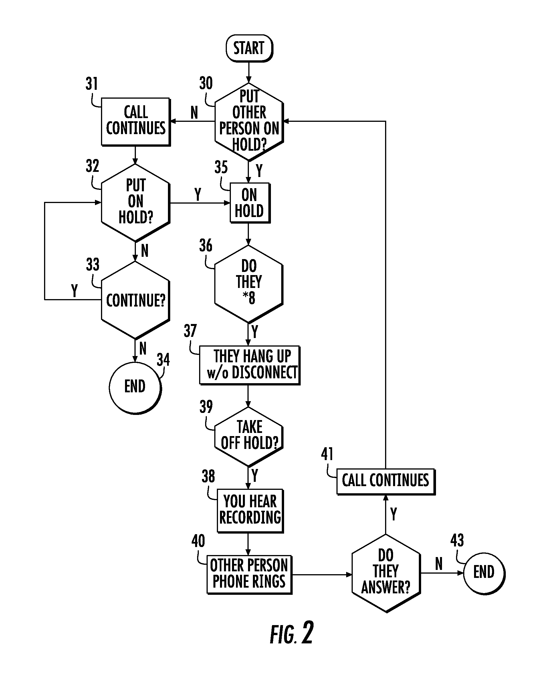
A telephone system provides an alternative to being kept “on hold”. When placed on hold, *8 or some can be dialed, which allows the party placed on hold to hang up his or her phone without disconnecting the call. To resume the call, the party that placed the call on hold dials any number on his or her phone and the phone of the party that had been placed on hold rings to signify that the call is off hold and can be resumed. When the call back is answered the call is resumed. In a first embodiment, the callback on hold operation is performed in cooperation with a telecommunication company's central office switch. In a second embodiment, dedicated circuitry and microprocessor firmware are added to consumer telephone equipment, performing the callback on hold operation without requiting any specific support from a central office switch. The present invention is disclosed in the environments of telephones, answering machines, combination telephone and answering machines, both corded and cordless telephones (with or without answering machines), cellular telephones, and standalone devices attachable between a telephone and/or answering system and the central office telephone lines. A “hold on hold” indicator lamp may optionally be employed. The indicator lamp circuitry detects brief DTMF tone pairs to signal the operation of a hold LED with a unique cadence indicating of a callback hold, rather than a normal hold condition.

Description

CROSS-REFERENCE TO RELATED APPLICATION[0001]This application claims the benefit of U.S. Provisional Patent Application No. 61 / 095,050, filed Sep. 8, 2008, the entirety of which is incorporated herein by reference.BACKGROUND OF THE INVENTION[0002]1. Field of the Invention[0003]The present invention relates, in general, to telephony and, more particularly, to an apparatus and a method for providing a call back or signal to a party placed on hold when a call is taken off hold.[0004]2. General Background of the Invention In conventional telephony systems, one party placed on hold by the other party upon initial connection, such as when a receiver of a telephone call places the caller on hold, the party placed on hold must simply wait for the hold to be removed, This inconveniences the caller placed on hold, and can result in the accrual of significant connect-time charges even though no meaningful communication is taking place during the time spent on hold.BRIEF SUMMARY OF THE INVENTION...

Claims


Application Information

Patent Timeline
IPC IPC(8): H04M1/00
CPCH04W4/16H04M3/4286
Inventor KOLE, RYANCROSLEY, THOMAS
Owner PHONE FEATURES
Why Eureka
Try Eureka