Site based quantification of substrate topography and its relation to lithography defocus and overlay

Active Publication Date: 2011-07-14
KLA TENCOR CORP
View PDF0 Cites 66 Cited by
  • Summary
  • Abstract
  • Description
  • Claims
  • Application Information

AI Technical Summary

Benefits of technology

[0008]A methodology and system therefore is presented herein for quantifying the substrate NT and

Problems solved by technology

Errors in lithography can result from in-the-plane distortions (which can result in overlay errors) or from out of the plane distortions, which can result in defocus.
The substrate NT parameters are seen to affect the lithography process, for example by contributing to defocus and ove

Method used


Image

  • Site based quantification of substrate topography and its relation to lithography defocus and overlay
  • Site based quantification of substrate topography and its relation to lithography defocus and overlay
  • Site based quantification of substrate topography and its relation to lithography defocus and overlay

Examples


Embodiment Construction

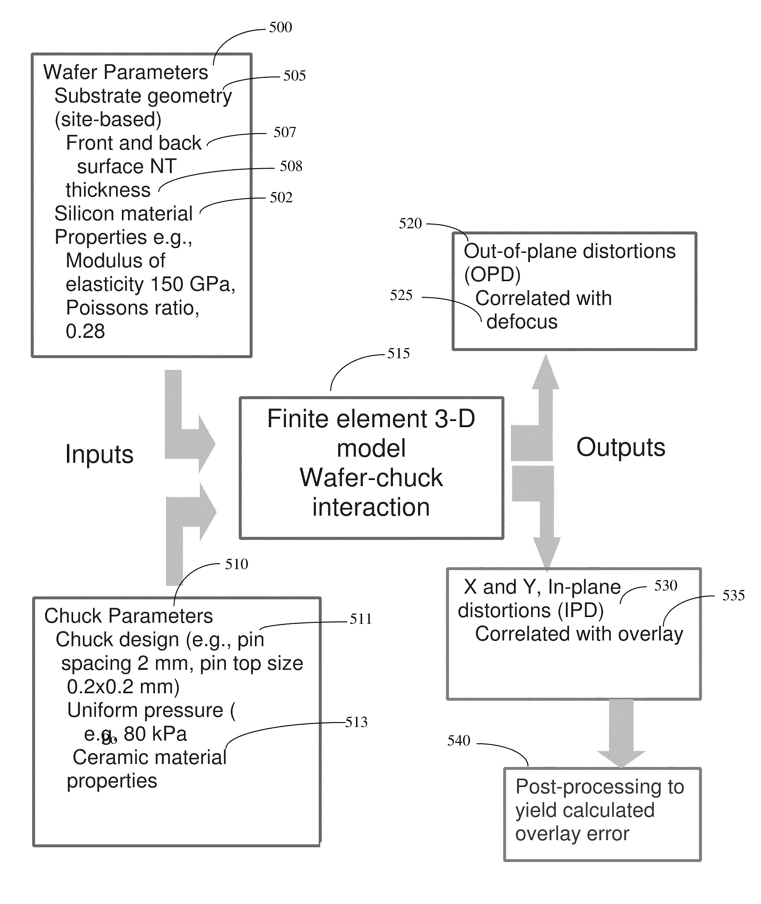
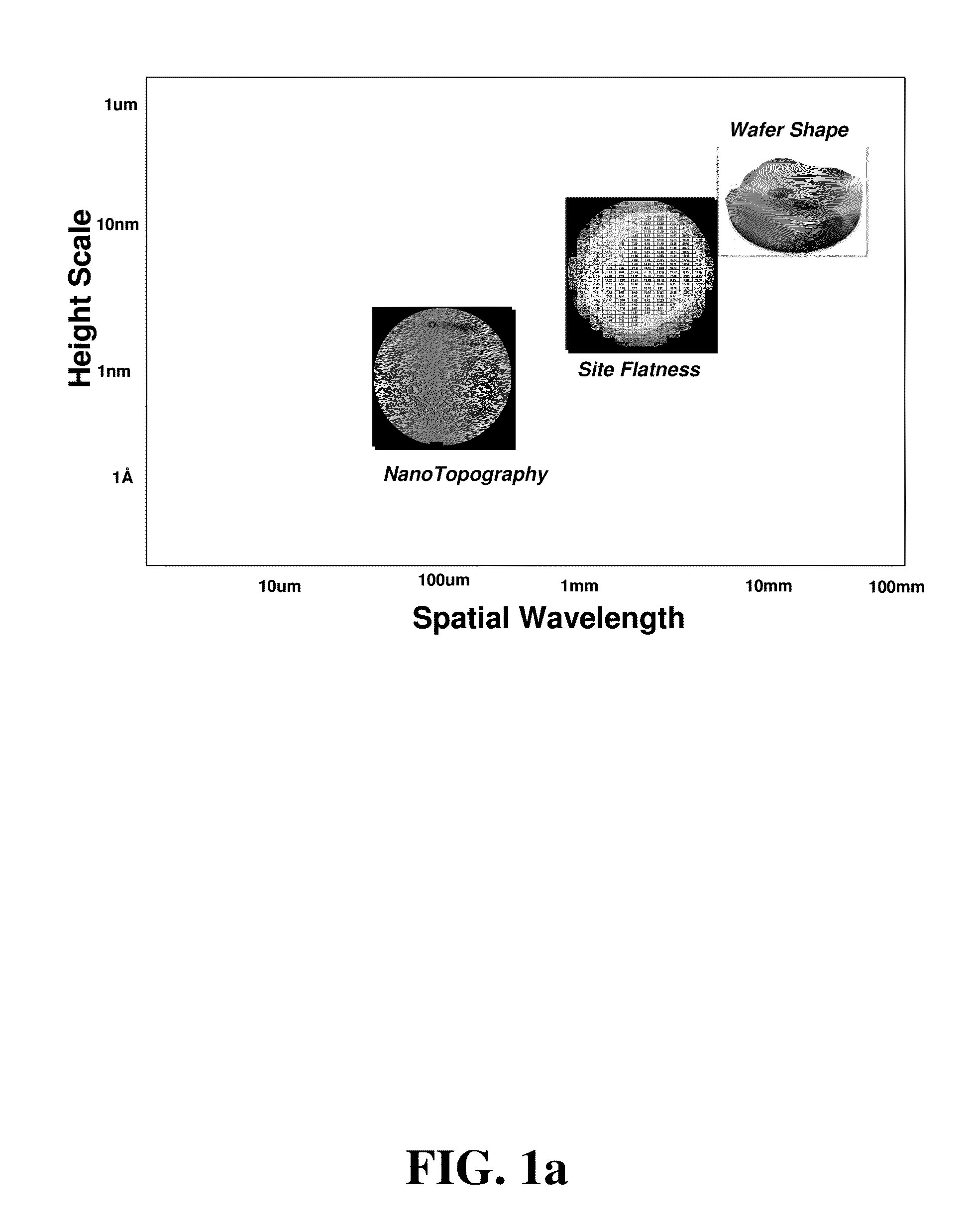
[0020]The method and system described herein provides for the measurement and quantification of wafer NT relevant to lithography with appropriate metrics (such as Peak-to-Valley (PV) range and RMS), and the effect of the NT on such parameters as lithography defocus and overlay error. The results obtained in this way enable the sorting and / or qualification of bare or patterned wafers for the process flow. Wafer qualification may be accomplished by comparing the quantified metric values to a user-determined threshold or cut-off, which may be determined at least in part by the process flow.

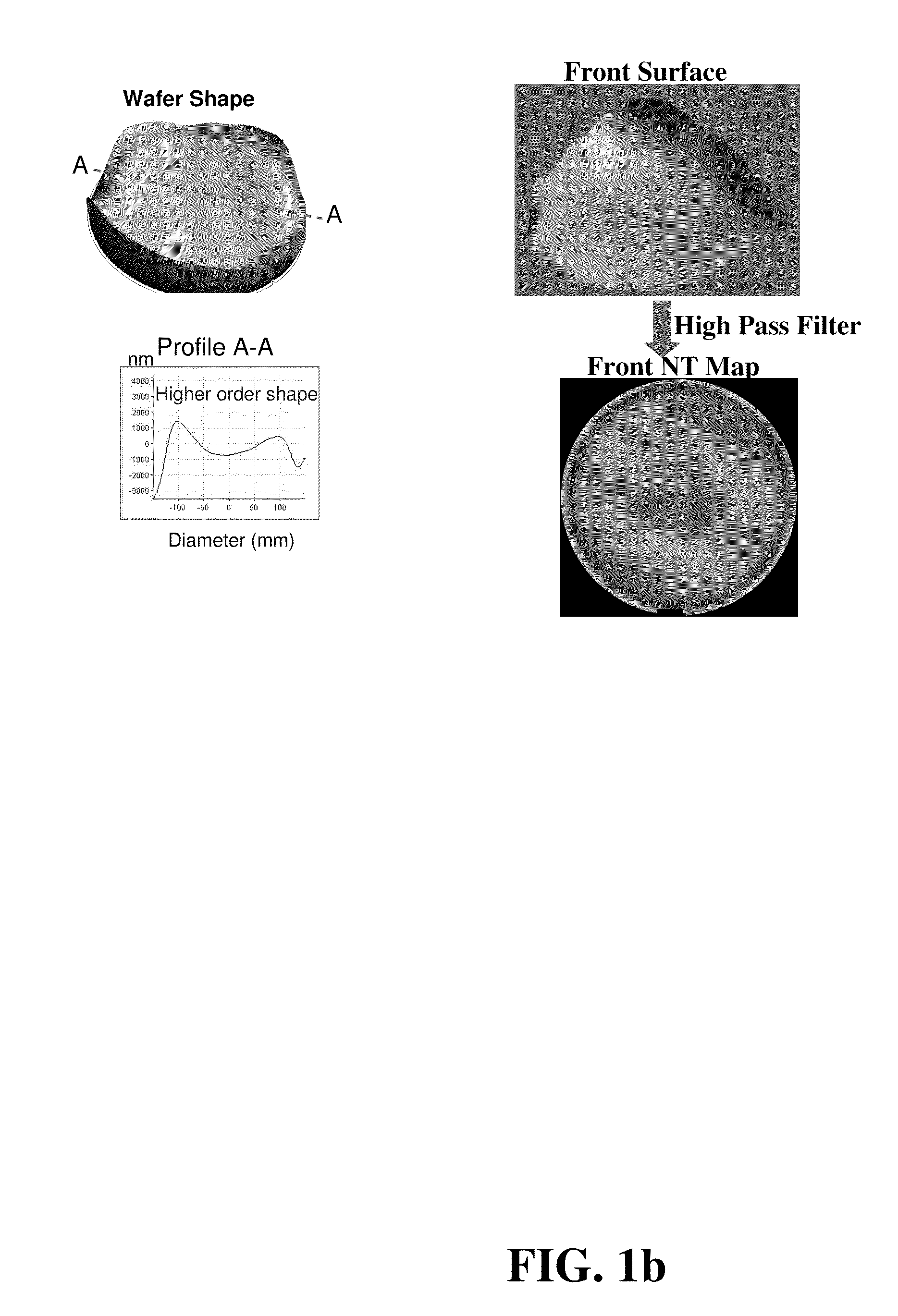
[0021]A first requirement for developing a quantification methodology for determining the influence of wafer topographical aspects such as NT or shape on lithographic overlay / defocus is to accurately measure the wafer front and back surface topography. Wafer measurement with the wafer in a free state, where front and back surface an be measured simultaneously, is preferred, since it eliminates possib...


PUM


Abstract

A method and system for modeling and analyzing wafer nanotopography data utilizes a nonlinear contact finite element model. Inputs to the model include lithography chuck parameters and site-based geometry data. Outputs from the model include in-plane distortions and out-of-plane distortions, from which defocus and overlay can be derived.

Description

CROSS-REFERENCE TO RELATED APPLICATIONS[0001]This application is related to U.S. Provisional application No. 61 / 293,548, filed Jan. 8, 2010, and claims priority thereto.FIELD OF THE INVENTION[0002]This invention relates to integrated circuit processing, and in particular to the characterization of wafer substrate topography and its relation to overlay and defocus errors in lithography.BACKGROUND[0003]As integrated circuits become faster and denser, requirements for lithography become increasingly stringent. Errors in lithography can result from in-the-plane distortions (which can result in overlay errors) or from out of the plane distortions, which can result in defocus. The necessity for verifying that a given wafer is sufficiently planar and within specifications, i.e. in qualifying and selecting wafers even before processing begins or during processing, is becoming ever greater. A critical component in the characterization of wafers is the wafer topography, sometimes termed subst...

Claims


Application Information

Patent Timeline
IPC IPC(8): G06F17/50
CPCG01N21/9501G06F17/5009G03F7/70633G03F7/705G01B11/24G03F7/70641G03F7/7065G03F7/70783H01L22/12G06F30/23G06F30/20
Inventor VEERARAGHAVAN, SATHISHSINHA, JAYDEEP
Owner KLA TENCOR CORP
Why Eureka
Try Eureka