
Master unit and slave unit

a slave unit and master technology, applied in the field of master units and slave units, can solve the problems of inability to change the authentication key that the slave unit retains from the one set at the time of manufacture of the slave unit, inability to secure security, and inability to ensure security

Inactive Publication Date: 2011-07-14
PANASONIC CORP
View PDF7 Cites 198 Cited by
  • Summary
  • Abstract
  • Description
  • Claims
  • Application Information

AI Technical Summary

Benefits of technology

[0025]According to the present embodiment, when slave units are newly added to a master unit, simply by inputting identification information of the respective slave units to the master unit, a registration process of the respective slave units can be performed so that the slave units are connected to the existing network. In addition, in an authentication process of the respective slave units to be performed after the registration process of the slave units, use of a common encryption key (unique key) allows authentication of the slave units to be terminated in a short time even when there are a large number of slave units to be registered.

Problems solved by technology

However, unless the slave unit has a function to receive an input of an authentication key from outside, the authentication key that the slave unit retains cannot be changed from the one set at the time of manufacture of the slave unit.
Accordingly, the security may not be secured.
However, the technology disclosed in Patent document 2 has a problem that, a Man in the Middle is present between a client and a server in a network and when the Man in the Middle manipulates a public key of the server, security cannot be secured.
Further, when a public encryption key is used, a time required for encrypting and decrypting is longer than that required in a common key encryption method.
Accordingly, when a plurality of slave units having low-end CPUs are to be authenticated, a time required for authenticating all the slave units becomes long.

Method used


Image

  • Master unit and slave unit
  • Master unit and slave unit
  • Master unit and slave unit

Examples


first embodiment

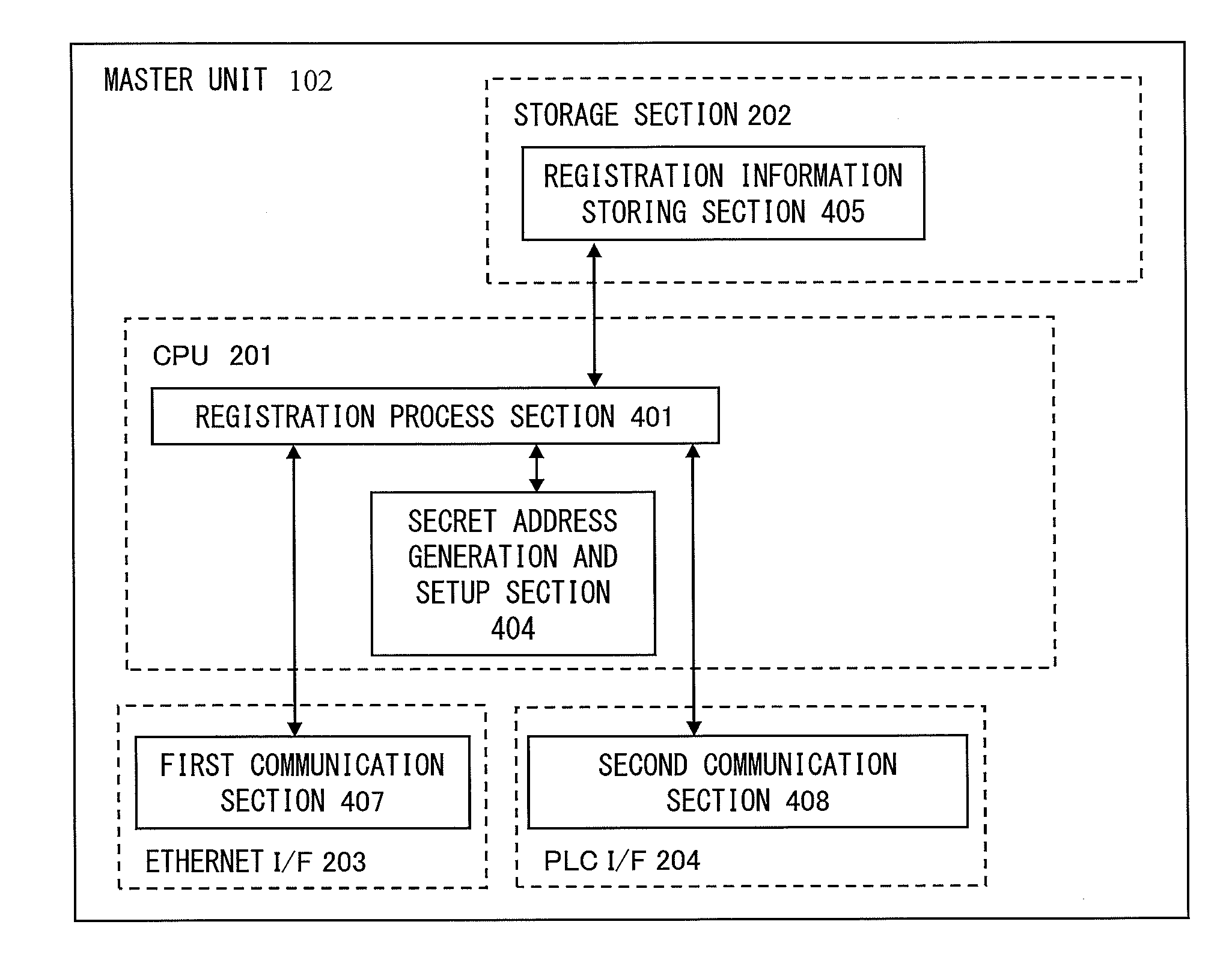
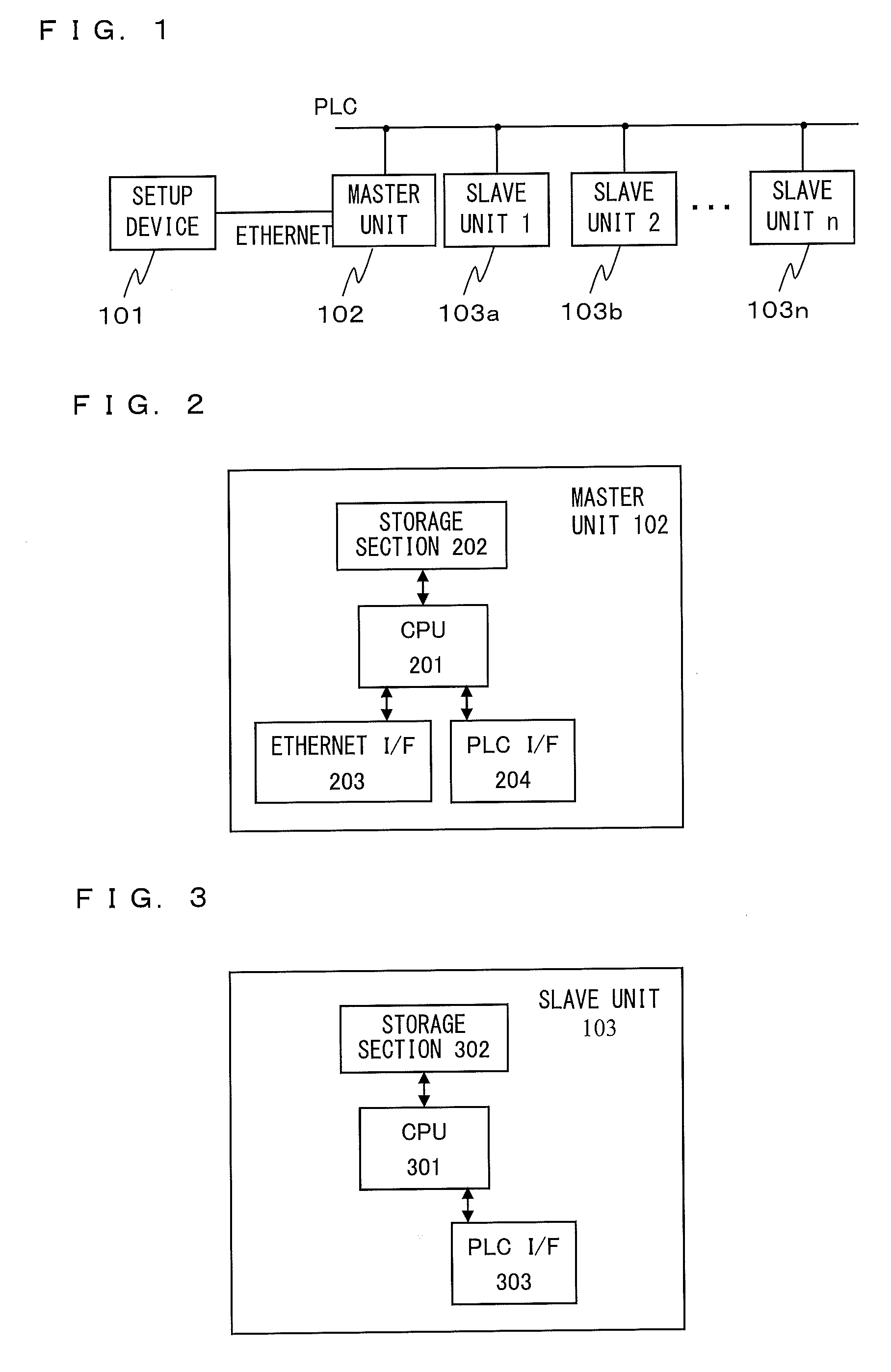
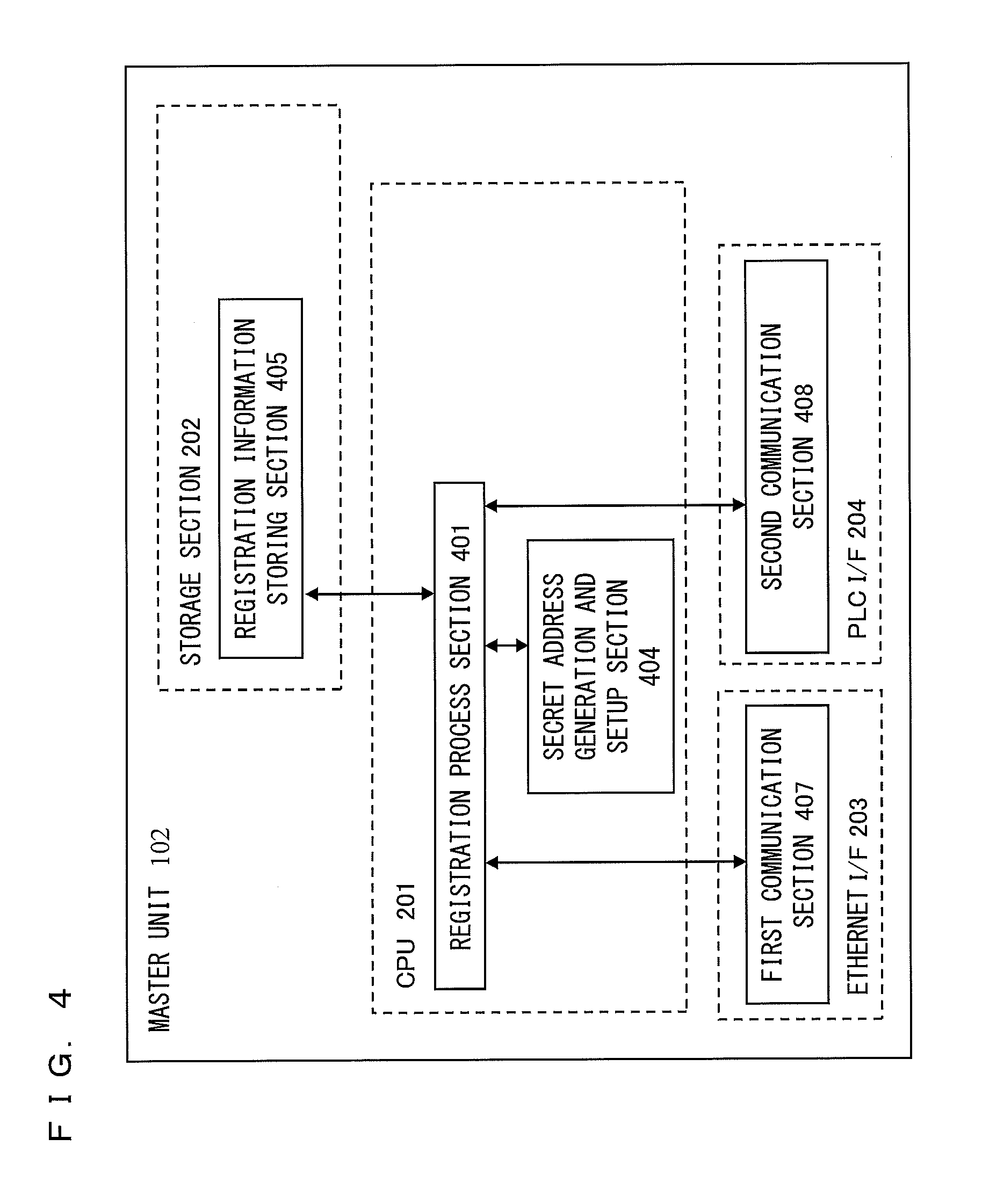
[0062]In a first embodiment, a registration process performed between a master unit 102 and each of slave units 103a to 103n will be described. FIG. 4 is a function block diagram showing functions of the master unit 102 in comparison with the physical configuration of the master unit 102 in FIG. 2. In FIG. 4, a CPU 201 has functions of a registration process section 401 and a secret address generation and setup section 404. A storage section 202 has a function of a registration information storing section 405. An Ethernet I / F 203 has a function of a first communication section 407. A PLC I / F 204 has a function of a second communication section 408. The registration information storing section 405 stores a unique address and a unique key of a slave unit 103 (that is, registration information of the slave unit 103) which has been registered.

[0063]The registration process section 401 performs a process in response to a command inputted via the first communication section 407, and, base...

second embodiment

[0123]In a second embodiment, procedures of an initial registration process and a re-registration process performed between a master unit 102 and each of slave units 103a to 103n are different from those in the first embodiment. Function block diagrams of the master unit 102 and the slave unit 103 are the same as those in the first embodiment, and thus descriptions will be made with reference to FIG. 4 and FIG. 5. In the following, only operations different from those in the first embodiment will be described.

[0124]FIG. 21 is a flow chart showing an initial registration process performed by a master unit 102 according to the second embodiment. In FIG. 21, the master unit 102 omits operations of step S1003, S1004, and S1014 which are performed in the initial registration process (see FIG. 10) according to the first embodiment. FIG. 22 is a flow chart showing an initial registration process performed by a slave unit 103 according to the second embodiment. In FIG. 22, the slave unit 10...

third embodiment

[0152]In a third embodiment, description will be made of an authentication process performed so that a communication key is shared between a master unit and a slave unit which already share a unique key. Upon termination of the initial registration process, each of slave units 103a to 103n can specify a unique address of a master unit 102 as a destination address, request the master unit 102 for the authentication process, and receives a communication key from the master unit 102. In the following, in addition to the initial registration process and a re-registration process, configurations of the master unit 102 and the slave unit 103 which perform the authentication process will be described. FIG. 27 is a function block diagram of a master unit 102 according to the third embodiment. In FIG. 27, a CPU 201 has, in addition to functions of a registration process section 401 and a secret address generation and setup section 404, a function of a communication authentication section 402...


PUM


Abstract

Provided is a communication device which securely registers a slave unit. A secret address generation and setup section generates a secret address generator, and a secret address of the slave unit used temporarily instead of a unique address of the slave unit based on the secret address generator and identification information of the slave unit. A second communication section transmits to the slave unit a registration start notice containing the secret address generator by broadcast. A registration process section generates a registration authentication key; generates a unique key of the slave unit by transmitting / receiving, to / from the slave unit, unique key generation information encrypted using the registration authentication key; receives, from the slave unit, the unique address of the slave unit encrypted using the registration authentication key; and stores the identification information in association with the unique address and the unique key of the slave unit in the registration information storing section.

Description

TECHNICAL FIELD[0001]The present invention is directed to a technology which can facilitate registration of a plurality of communication devices (slave units) by a communication device (master unit) in a communication network.BACKGROUND ART[0002]In a communication network such as a wireless communication or a PLC (Power Line Communications), in order to prevent information leakage to the outside of the network, a commonly used method is to perform an authentication process for sharing an encryption key to be used in communication between a communication device which currently participates in the network and a communication device which tries to newly participate in the network, and once the authentication process is terminated, to conduct communication by encrypting data using the shared encryption key.[0003]In one example of the authentication process, a user sets a common authentication key both in a slave unit which requests for authentication and a master unit which authenticate...

Claims


Application Information

Patent Timeline
IPC IPC(8): H04L9/32G06F21/31G06F21/44
CPCH04B3/542H04L2209/80H04L9/0844Y04S40/20
Inventor ZHANG, YIBO
Owner PANASONIC CORP
Learn More