
Portable electrical power source for incorporation with an armored garment

a power source and armored garment technology, applied in shields, cell components, electrochemical generators, etc., can solve the problems of power supplies that lack functionality beyond common batteries, and achieve the effect of enhancing ballistic protection of armored garments

Inactive Publication Date: 2011-07-21
BAE SYST AEROSPACE & DEFENSE GROUP
View PDF83 Cites 17 Cited by
  • Summary
  • Abstract
  • Description
  • Claims
  • Application Information

AI Technical Summary

Benefits of technology

[0006]The armored plate may provide ballistic protection to a user of an armored garment that incorporates the armored plate. When positioned proximally and face-to-face, the power plate may enhance the protectiveness of the armored plate. For example, a ballistic projectile that first strikes the power plate may be decelerated, shattered, or deflected to some degree (e.g., twist), thereby reducing energy transmitted to the armored plate.
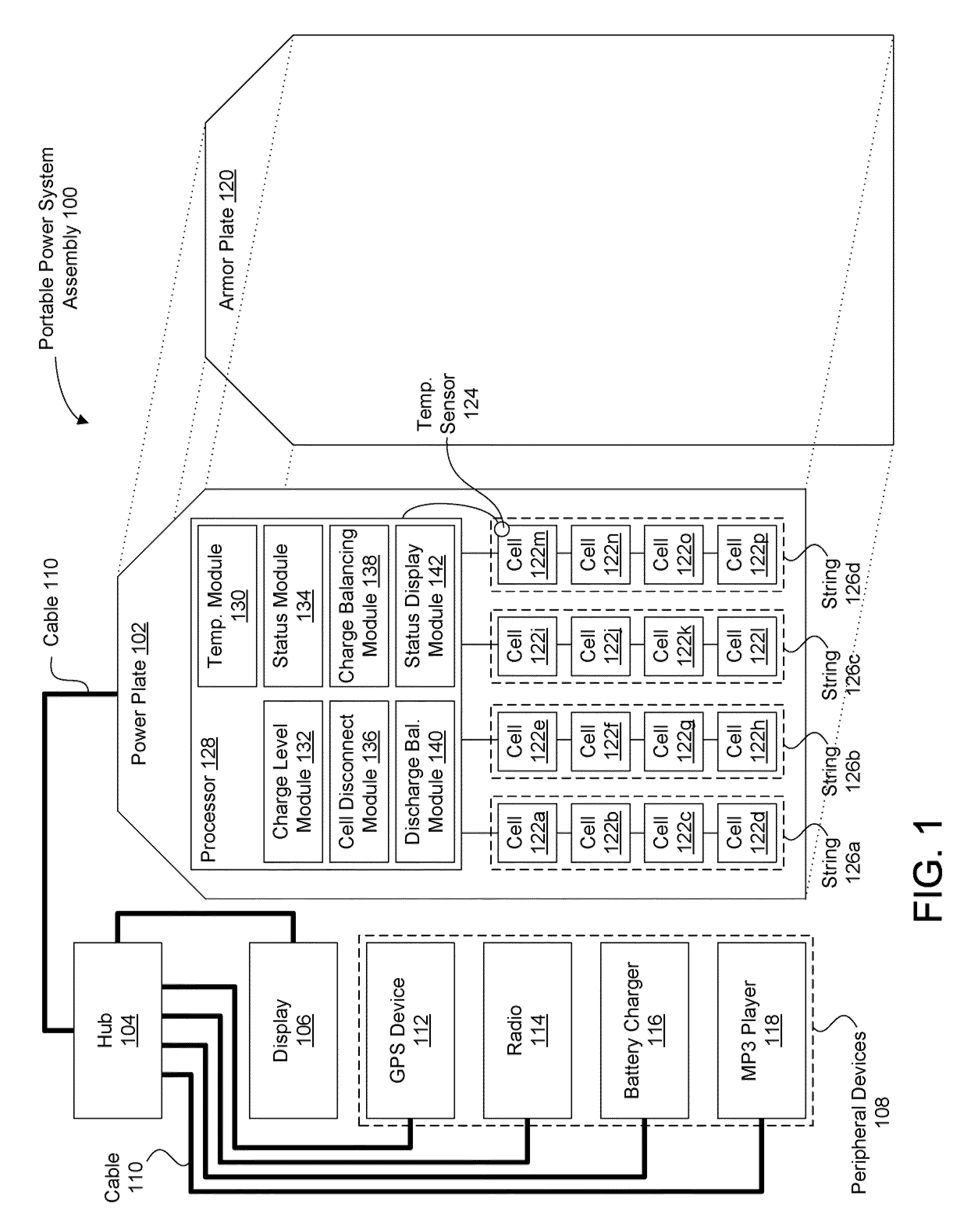
[0010]The strings may include any configuration such as a linear array of cells or a rectangular array of cells. The cells that are respectively included in each of the strings may be connected in series, in parallel, or in another configuration. The strings may be connected in series, in parallel, or in another configuration. Additionally, the strings may be isolated from each other so that they are not interconnected. By segregating the strings, performance of the power plate may be maintained, even when one or more of the strings become disabled, such as in the event of ballistic impact on one of the strings. Furthermore, wires and / or cables routed to the cells may be segregated so as to minimize wire and / or cable failure in the event of ballistic impact on a wire or cable.
[0017]The cell disconnect module may be configured to disconnect one or more of the cells having a fault associated therewith, such as that determined through execution of the status module. By disconnecting a cell having a fault, performance of the portable power system assembly may be maintained. For example, catastrophic failure of a cell such as an explosion or cell ignition may be prevented. Furthermore, leakage of damaged cells may be halted or minimized. Additionally, by disconnecting a cell having a fault, the remaining cells may be prevented from becoming faulty or otherwise damaged.
[0019]Controlling the charge power level during charging of the cells may extend lifetime and maintain proper performance of the cells, as well as prevent overheating. Controlling charge power level of each cell may minimize or greatly reduce charging times. For example, controlling the charge power level may prevent against overcharging where a cell's capacity is exceeded, overvoltage where the cell voltage exceeds an upper design limit, and / or overcurrent where the current delivered to the cell exceeds an upper design limit. To illustrate controlling a charge power level, if one cell is at 80% capacity and the remaining cells are each at 98% capacity, the charge balancing module will prevent excessive current from being provided to the one cell during charging while the capacity of the one cell is brought up to match that of the remaining cells.
[0021]Controlling the discharge power level during discharging of the cells may extend lifetime and maintain proper performance of the cells, as well as prevent safety risks. For example, controlling the discharge power level may prevent against deep discharging where a cell is completely drained or rapid discharges due to shorted circuitry. To illustrate controlling a discharge power level, if the power plate is utilized to provide electrical power to a lamp that is left on for an extended period of time, the discharge balancing module may prevent the cells from becoming completely drained.
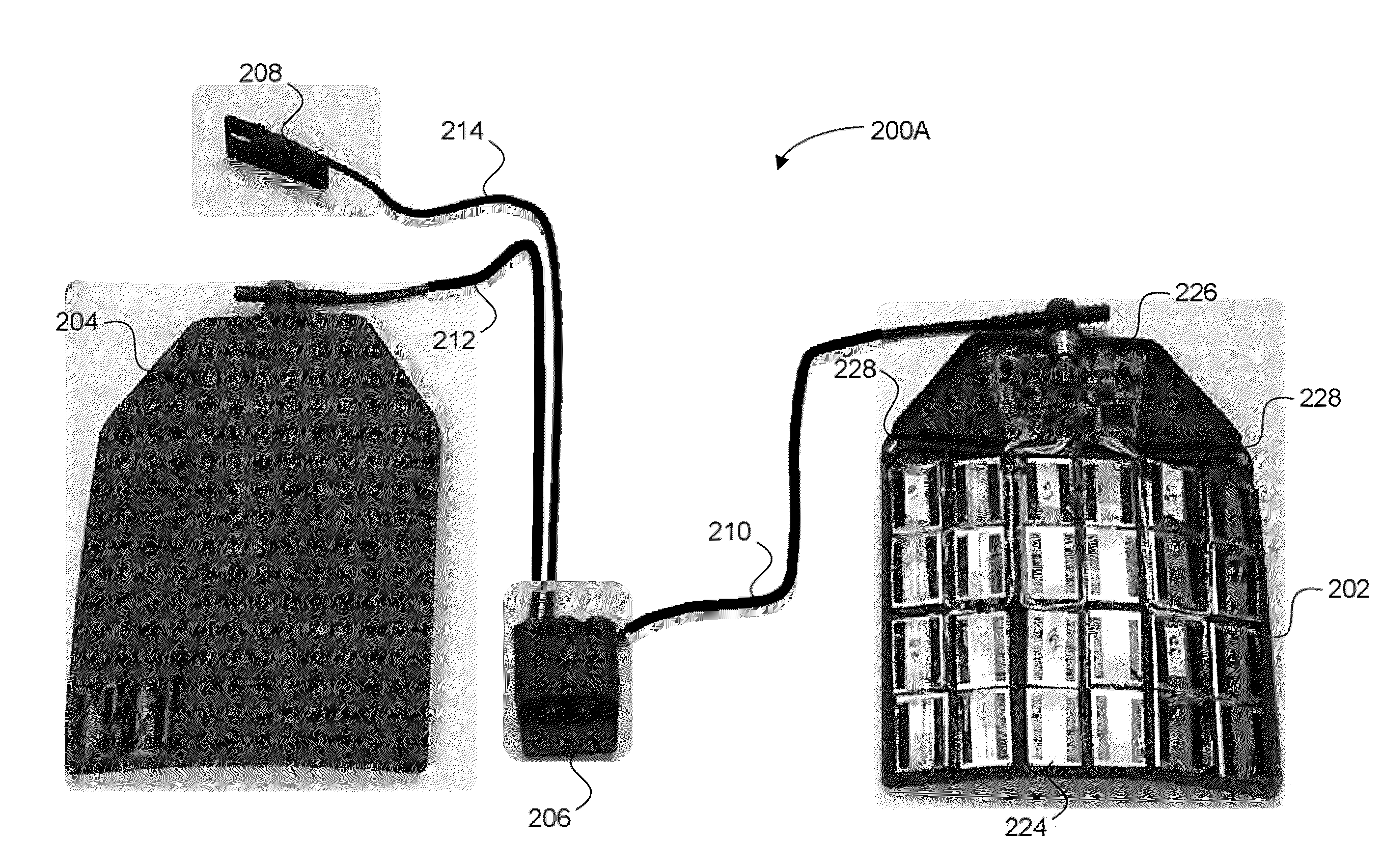
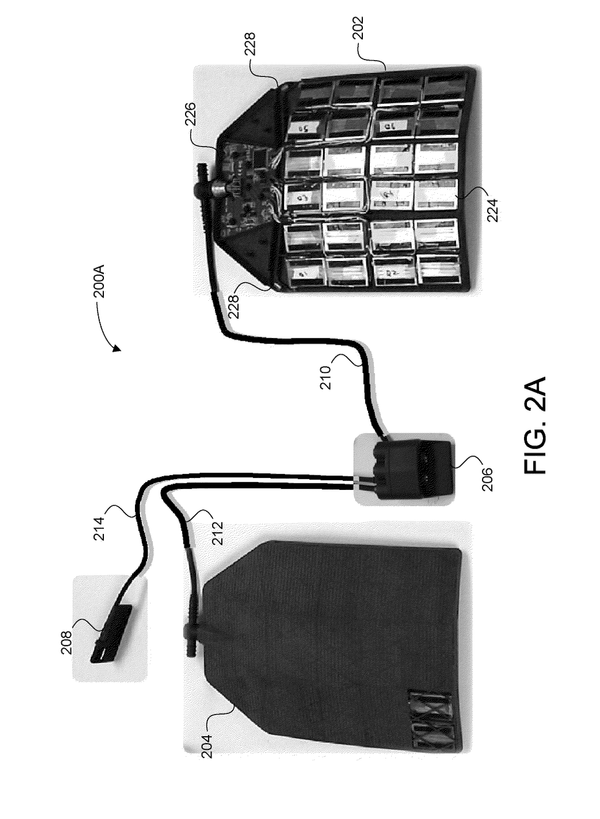
[0023]Another aspect of the invention relates to an armored garment that incorporates an electrical power source. The armored garment may include an armor plate situated in the garment to provide ballistic protection to the front of the upper abdomen of a wearer of the garment. The armored garment may further include a sleeve disposed on the garment outside of the armor plate. The sleeve may be configured to secure an electrical power source to the garment having a footprint that corresponds to a footprint of the armor plate. The sleeve may have an opening through which the electrical power source is insertable and removable to the sleeve. The opening may be formed on a side of the sleeve opposite the head of a wearer of the garment while the garment is being worn by the user. The armored garment may further include a pouch configured to at least partially enclose the electrical power source within the sleeve. The electrical power source may enhance ballistic protection of the armored garment.

Problems solved by technology

These power supplies, however, lack functionality beyond common batteries.
Such a fault may be based on any failure mode or other state of inoperability of one or more of the cells.

Method used


Image

  • Portable electrical power source for incorporation with an armored garment
  • Portable electrical power source for incorporation with an armored garment
  • Portable electrical power source for incorporation with an armored garment

Examples


Embodiment Construction

[0037]FIG. 1 illustrates a block diagram of an exemplary implementation of a portable power system assembly 100. The portable power system assembly 100 may include a power plate 102, a hub 104, a display 106, and peripheral devices 108. The power plate 102 serves as a power source and provides electrical power to the peripheral devices 108 via the hub 104. Cables such as cables 110 may couple the power plate 102, the hub 104, the display 106, and the peripheral devices 108. The cables 110 may include any wire, cable, or other hardware suitable for allowing electrical power and information to be transferred between the power plate 102, the hub 104, the display 106, and the peripheral devices 108. According to exemplary implementations, any device (e.g., the power plate 102, display 106, and / or the peripheral devices 108) may be connected to the hub 104 without identifying or “keying-in” that device. The display 106 may be any device suitable for visually conveying dynamic information...


PUM


Abstract

An apparatus may be configured to provide electrical power while incorporated in an armored garment. The apparatus may include a plate having a footprint that corresponds to a plate of body armor, a plurality of energy storage cells carried by the power plate, and a port carried by the plate. The port may be configured to output power stored in the plurality of energy storage cells from the apparatus. The apparatus may also include one or more processors configured to enhance functionalities of the apparatus.

Description

FIELD OF THE INVENTION[0001]The invention relates to a portable electrical power source that can be incorporated with an armored garment.BACKGROUND OF THE INVENTION[0002]Military and law enforcement personnel often wear armored garments such as bullet-resistant vests while on duty. The use of devices that require electrical power in order to operate is becoming more and more common among military and law enforcement personnel. Some armored garments incorporate power supplies to provide electrical power to such devices. These power supplies, however, lack functionality beyond common batteries.SUMMARY[0003]One aspect of the invention relates to a portable power system assembly. The portable power system assembly may include a power plate, a hub, a display, and peripheral devices. The power plate serves as a power source and provides electrical power to the peripheral devices via the hub. Cables such as cables may couple the power plate, the hub, the display, and the peripheral devices...

Claims


Application Information

Patent Timeline
IPC IPC(8): F41H1/02F41H5/02H01M10/48H01M2/00H02J7/00H01M50/211H01M50/238H01M50/247H01M50/296
CPCF41H1/02H01M2/1022H01M2010/4271H01M10/482H01M10/486H01M10/441Y02E60/10H01M50/247H01M50/296H01M50/238H01M50/211
Inventor MCELROY, MICHAELHORVATICH, VALENTCOLTMAN, III, JOSEPH WESLEYFURTH, DANIELSEGO, JR., KENNETHVON DER AHE, KENNETH LEEHOENES, ERIC
Owner BAE SYST AEROSPACE & DEFENSE GROUP
Learn More