Valve timing adjuster

Inactive Publication Date: 2011-07-21
DENSO CORP
View PDF18 Cites 11 Cited by
  • Summary
  • Abstract
  • Description
  • Claims
  • Application Information

AI Technical Summary

Problems solved by technology

If the pulley has the cup shape, the timing belt, which engages with the outer periphery of the pulley, radially inwardly applies load to the outer wall of the pulley, resulting in the deformation of the pulley.
When the pulley is leaning due to the deformation caused by the above load, the timing belt may be erroneously displaced.
Thus, in order to prevent the deformation, it is required to make the outer wall thicker, and thereby the valve timing adjuster becomes greater in weight disadvantageously.
Therefore, even when the timing belt is light weight, the total weight of the valve timing adjuster having the timing belt and the pulley becomes greater.
As a result, the cup-shaped pulley may degrade the fuel efficiency when mounted on the vehicle.
Furthermore, the timing belt has poor durability although the timing belt has the certain advantages as above.
For example, if a porous metal sintered body is used for the outer casing component of the valve timing adjuster, oil may leak.
As a result, the manufacturing cost increases.
However, in the above alternative case, the product weight may be increased, or the manufacturing cost may increase.

Method used


Image

  • Valve timing adjuster
  • Valve timing adjuster
  • Valve timing adjuster

Examples


first embodiment

(First Embodiment)

[0028]The first embodiment of the present invention will be described with reference to FIGS. 1 to 7.

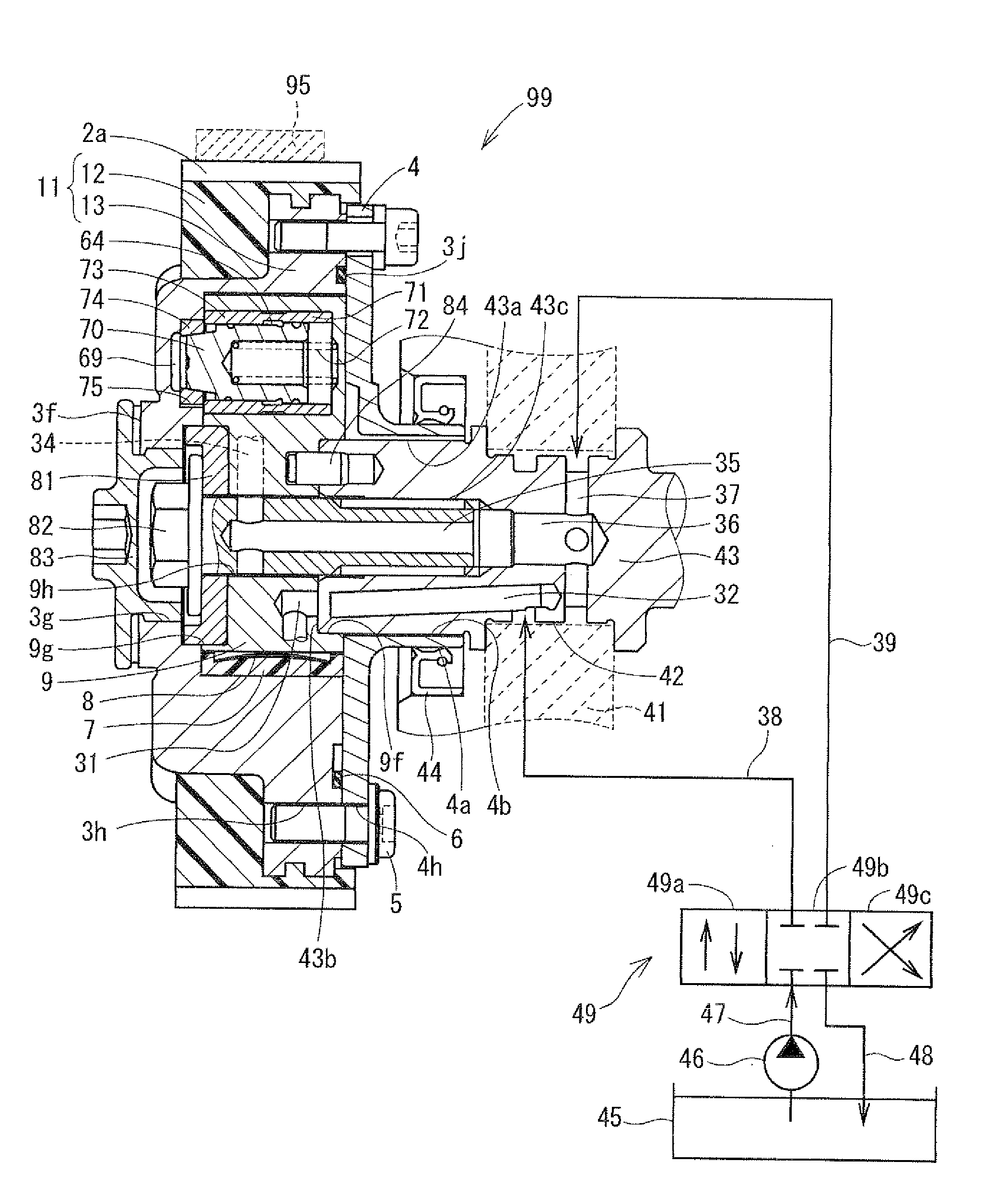
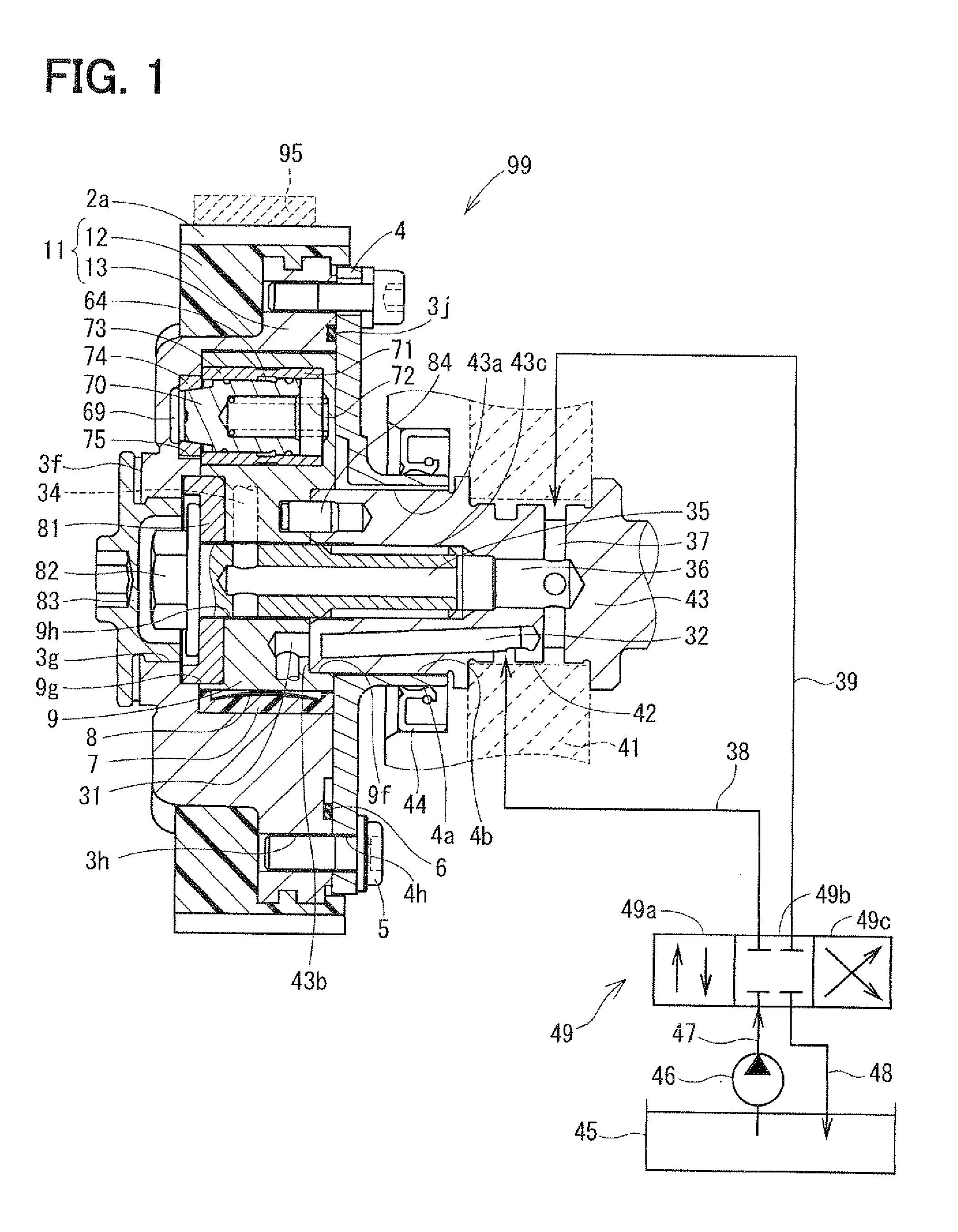
[0029]FIG. 1 is a cross-sectional view illustrating a valve timing adjuster according to the first embodiment of the present invention, and illustrates a state, where the valve timing adjuster is assembled to a camshaft. FIG. 1 also illustrates an oil pressure supply circuit. FIG. 1 will be detailed later.

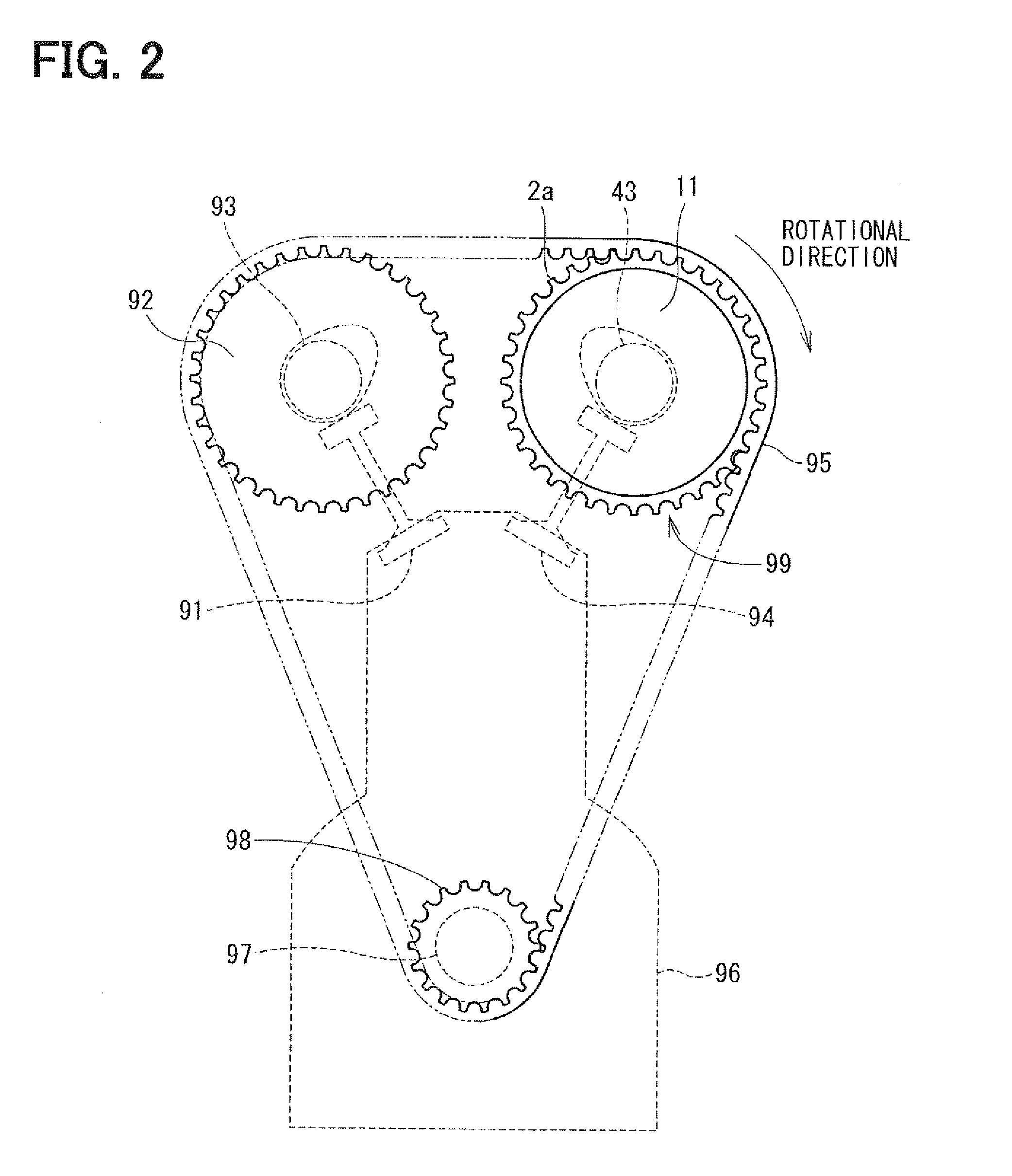
[0030]In FIG. 2, an internal combustion engine 96 includes a crankshaft 97 and a camshaft 43. The crankshaft 97 corresponds to a “drive shaft”, and the camshaft 43 is provided to an intake valve 94 and corresponds to a “driven shaft”.

[0031]A valve timing adjuster 99 is applied to the intake valve 94 and opens and closes the intake valve 94 by a predetermined phase difference from the crankshaft 97. The valve timing adjuster 99 includes a pulley-integrated housing 11, and the pulley-integrated housing 11 includes a “pulley part” and a “housing formed integrally with...

second embodiment

[0105]A pulley assembly of a valve timing adjuster according to the second embodiment of the present invention will be described with reference to FIGS. 8 and 9. FIG. 8 is a front view of a pulley assembly 20, and FIG. 9 is a cross-sectional view taken along line IX-IX of FIG. 8. It should be the configuration and operation of the present embodiment are similar to those in the first embodiment otherwise noted.

[0106]A pulley-integrated housing 21 is made through an aluminum sintering process or an aluminum extrusion process. The aluminum sintering process is a method for forming the pulley-integrated housing 21 by sintering aluminum powder in the molding die. The extrusion process is a method for forming the pulley-integrated housing 21 by continuously forming an elongated product having a uniform cross section in the longitudinal direction thereof, and then cutting the elongated product by a predetermined length. In the either method, a primary work piece of the pulley-integrated ho...


PUM


Abstract

A valve timing adjuster is mounted to a driving force transmission system, wherein the driving force transmission system transmits a driving force through a timing belt from a drive shaft to a driven shaft. The timing belt is rotatable synchronously with rotation of the drive shaft. The valve timing adjuster includes a pulley part, a housing, and a vane rotor. The pulley part is rotatable synchronously with the drive shaft through engagement with the timing belt. The housing is formed integrally with the pulley part. The vane rotor is received within the housing. The vane rotor is rotatable synchronously with the driven shaft. The vane rotor has a plurality of vane parts that is rotatable relative to the housing within a predetermined angular range.

Description

CROSS REFERENCE TO RELATED APPLICATION[0001]This application is based on and incorporates herein by reference Japanese Patent Application No. 2010-10172 filed on Jan. 20, 2010 and Japanese Patent Application No. 2010-269193 filed on Dec. 2. 2010.BACKGROUND OF THE INVENTION[0002]1. Field of the Invention[0003]The present invention is related to a valve timing adjuster that changes valve timing of opening and closing at least one of an intake valve and an exhaust valve.[0004]2. Description of Related Art[0005]A conventional vane-type valve timing adjuster opens and closes at least one of an intake valve and an exhaust valve based on a phase difference. The valve timing adjuster generates the phase difference based on a relative rotation between (a) a camshaft and (b) a timing pulley, or a relative rotation between (a) the camshaft and (b) a sprocket, by driving the camshaft through the timing pulley or the sprocket. Typically, the timing pulley and the sprocket rotate synchronously wi...

Claims


Application Information

Patent Timeline
IPC IPC(8): F01L1/344
CPCF01L1/024F01L1/0532F01L1/3442F01L2001/0537F01L2103/00F01L2001/3443F01L2001/34469F01L2001/34479F01L2001/34426F01L2301/00F01L2303/00F01L1/344F02D13/0219
Inventor TADA, KENJI
Owner DENSO CORP
Why Eureka
Try Eureka