Monitoring device and monitoring method
a monitoring device and numerical value technology, applied in the direction of liquid/fluent solid measurement, biomass after-treatment, enzymology, etc., can solve the problems of high complexity of the temperature correction algorithm, the inability to adequately enhance the reliability and reproducibility of the measurement result of the subject substance, and the inability to accurately cancel the influence accompanying the fluctuation. achieve the effect of high reliability and high reproducibility
- Summary
- Abstract
- Description
- Claims
- Application Information
AI Technical Summary
Benefits of technology
Problems solved by technology
Method used
Image
Examples
first working example
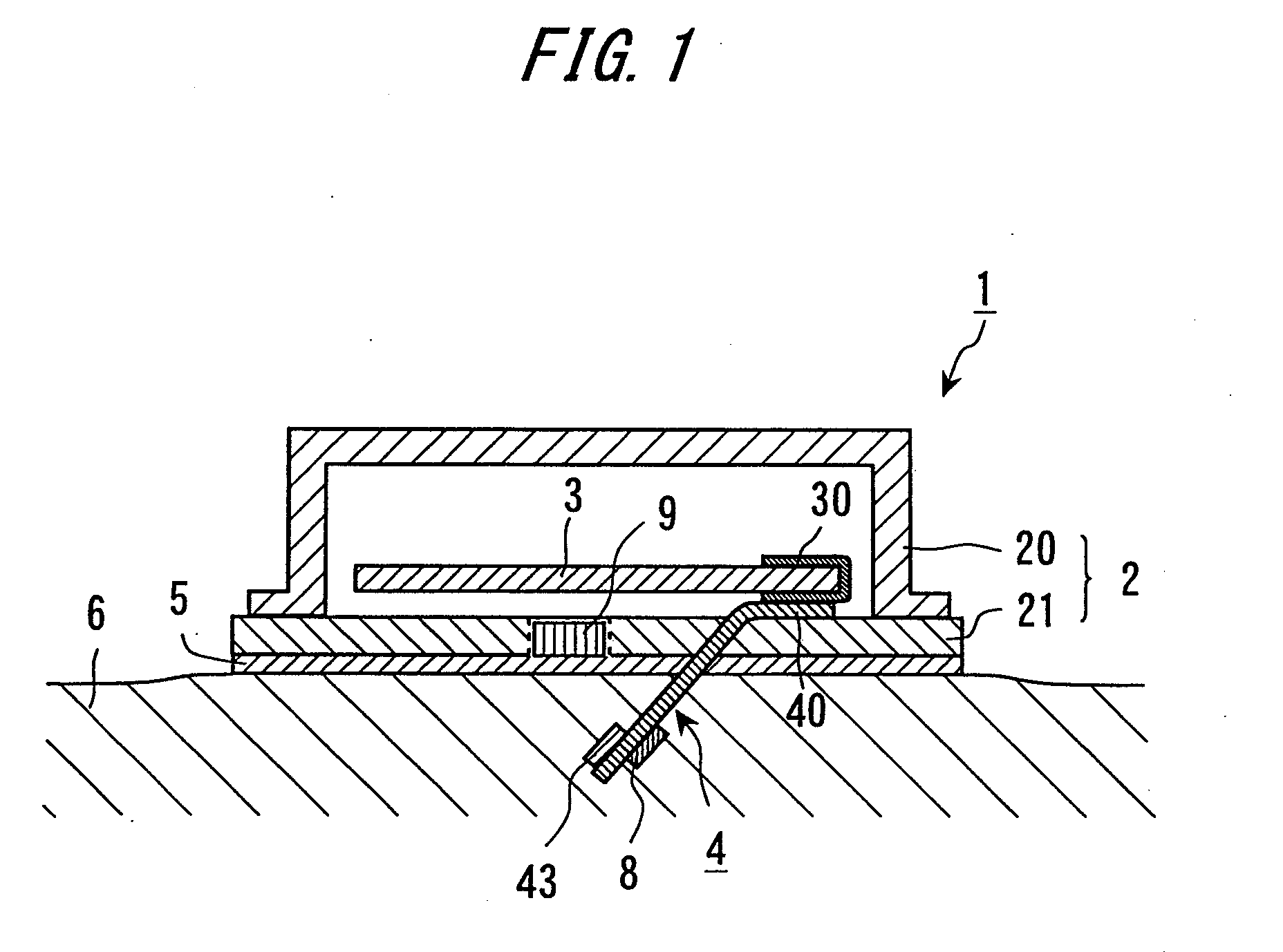
[0075]FIG. 1 is a view illustrating an outline of a configuration of the continuous glucose monitoring (abbreviated to CGM) device (which will hereinafter simply be termed “the monitoring device” or “measuring device”) in a first working example. A monitoring device 1 is capable of continuously measuring a glucose concentration in a blood and an interstitial liquid. The monitoring device 1 can be used in the way of being preferably attached to a skin of, e.g., an abdomen region and an arm region of a human body (examinee) but is not limited to this usage mode. This monitoring device 1 includes a housing 2, a control computer 3 and an electrochemical sensor 4.
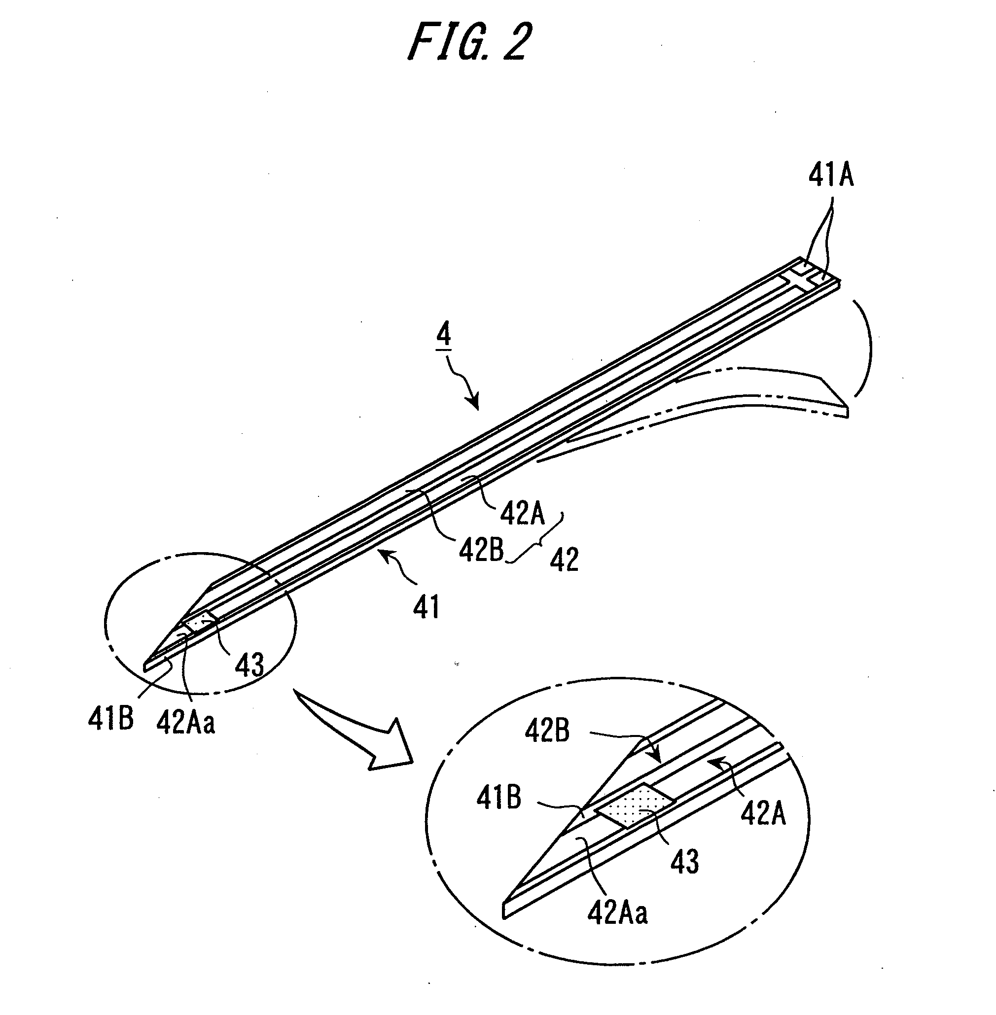
[0076]This electrochemical sensor 4 is a sensor which detects a specified subject substance by making use of electrochemical sensor reaction. The electrochemical sensor 4 in the first working example is classified as a so-called biosensor. The biosensor is a sensor which measures and detects the subject substance in a way that i...
second working example
[0124]Herein, a second working example will be described with reference to FIG. 8. FIG. 8 is an explanatory diagram for illustrating layout positions of the temperature sensor 8, the Peltier device 9 and the temperature control unit 13 according to the second working example. The second working example is common to the first working example except a point that the layout positions of the respective components are different from those in the first working example. The discussion will be focused on the different point from the already-described working example, and the explanations of the common points are omitted.
[0125]In the layout example illustrated in FIG. 1, the temperature control unit 13 and the Peltier device 9 are disposed in the housing 2 which accommodates the control computer 3, and the temperature sensor 8 is disposed in the glucose sensor 4. Note that the housing 2 can be said to be, in other words, the housing 2 which accommodates the sensor control unit 12. In the sec...
third working example
[0127]A third working example will be described with reference to FIG. 9. FIG. 9 is an explanatory diagram for illustrating layout positions of the temperature sensor 8, the Peltier device 9 and the temperature control unit 13 according to the third working example. A different point of the layout positions of the respective components in the third working example from FIG. 1 is that the housing 2 accommodates the temperature sensor 8 in addition to the Peltier device 9. Further, the temperature control unit 13 is the same as in the example illustrated in FIG. 1. In FIG. 9, the temperature sensor 8 is disposed in, e.g., the notched portion (the recessed portion or the cavity) of the base plate 21 in the same way as the Peltier device 9 is.
[0128]The temperature sensor 8 in the third working example is disposed not subcutaneously but on the skin surface, and hence the temperature measured by the temperature sensor 8 is substantially coincident with the temperature of the skin surface....
PUM
| Property | Measurement | Unit |
|---|---|---|
| Temperature | aaaaa | aaaaa |
| Electric properties | aaaaa | aaaaa |
Abstract
Description
Claims
Application Information
 - R&D
- Intellectual Property
- Life Sciences
- Materials
- Tech Scout
- Unparalleled Data Quality
- Higher Quality Content
- 60% Fewer Hallucinations
Browse by: Latest US Patents, China's latest patents, Technical Efficacy Thesaurus, Application Domain, Technology Topic, Popular Technical Reports.
© 2025 PatSnap. All rights reserved.Legal|Privacy policy|Modern Slavery Act Transparency Statement|Sitemap|About US| Contact US: help@patsnap.com


