Angular dependent pixels for trick view

a technology of trick view and angular dependence, which is applied in the field of display devices with electronically switchable privacy functions, can solve the problems of inefficient display in light use, and inability to control the brightness of the display film, so as to achieve a stronger privacy function and reduce colour variation

Inactive Publication Date: 2011-07-21
SHARP KK
View PDF4 Cites 34 Cited by
  • Summary
  • Abstract
  • Description
  • Claims
  • Application Information

AI Technical Summary

Benefits of technology

[0047]An advantage of the invention is that the use of additional optics to create different pixels with different angular dependent luminance functions (i.e. multi-directional pixels), in conjunction with image processing techniques, enables an electronically switchable privacy function for any type of pixelated image display. The universal applicability of the invention to provide a switchable privacy function for any type of pixelated information display has commercial advantage. A further advantage is the use of additional optics to create multi-directional pixels, in conjunction with image processing techniques, to enable a switchable privacy effect in display types which have a linear off-axis to on-axis luminance characteristic of the type described in GB2457106A. Without the use of additional optics to create multi-directional pixels, displays with a linear off-axis to on-axis luminance characteristic would not be able to provide a privacy effect according to the methods described in GB2457106A.
[0048]A further advantage is that image processing ...

Problems solved by technology

These technologies share the disadvantage that the light control film always absorbs a significant fraction of the light incident upon it, whether the display is in public or private mode.
The display is therefore inefficient in its use of light.
Another disadvantage relates to the power consumption of these devices.
This is a disadvantage for displays which are used for most of the time in the public mode.
Additional thickness is very undesirable, particularly in mobile display applications such as mobile phones and laptop computers.
These devices provide the switchable privacy function without the need for added displa...

Method used


Image

  • Angular dependent pixels for trick view
  • Angular dependent pixels for trick view
  • Angular dependent pixels for trick view

Examples


first embodiment

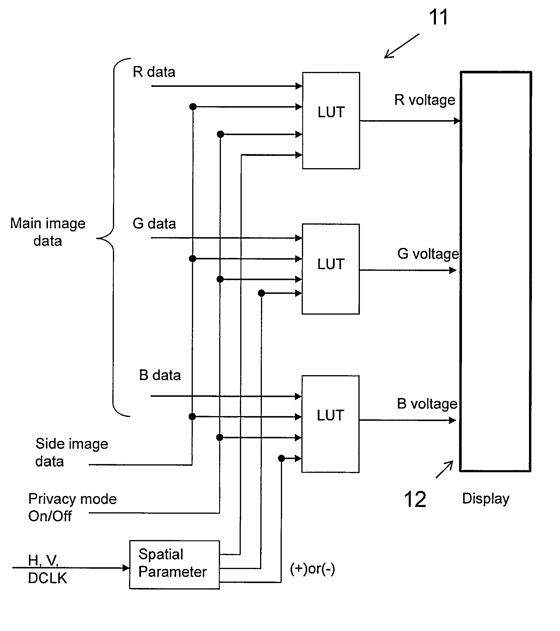
[0083]the invention relates to the use of additional optics in conjunction with the image processing technique as described in GB2428152A1, to enhance the privacy strength of a display device 1. In order to implement the image processing technique, the display controller electronics may be substantially as those described above for the switchable privacy display of GB2457106A. The display controller electronics may use the spatial “flag” parameter to denote which of the two or more pixel types of the display with differing luminance against viewing angle response is being addressed, rather than to denote which of two or more groups the pixel is deemed to be in based on solely on its spatial position. The display controller electronics may use the spatial “flag” parameter as described in GB2457106A and a secondary “flag” parameter to denote which of the two or more pixel types of the display with differing luminance against viewing angle response is being addressed. In this case, the...

second embodiment

[0095]Some display devices, such as IPS LCD and OLED, have a luminance-data response that is not intrinsically compatible with the image processing technique described in GB2428152A1 and hence a private narrow view mode can't be realised for these display devices using the image processing technique described in GB2428152A1. the invention relates to the use of additional optics with display types that are not intrinsically compatible with the image processing technique as described in GB2428152A1 so that a switchable privacy function can be realised for the display types.

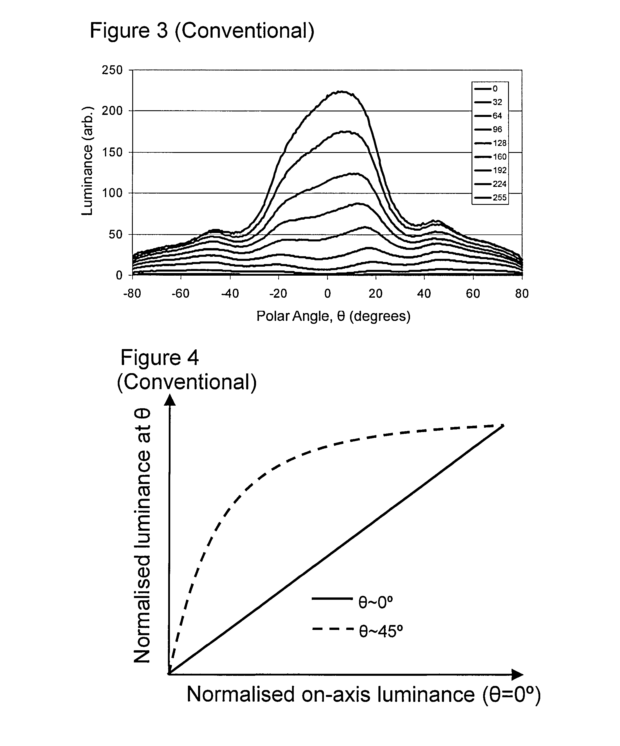
[0096]The plot in FIG. 13 illustrates a typical Normalised luminance at θ against Normalised on-axis luminance of a single pixel in either an in-plane switching (IPS) LCD or an OLED. Contrary to FIG. 4, the plot in FIG. 13 illustrates that there is very little intrinsic difference between the on-axis normalised luminance and off-axis normalised luminance response for the display types. For any normalized on-axis lum...

third embodiment

[0097]the invention relates to the use of additional of optics in conjunction with the image processing technique as described in GB2428152A1 to create a display device capable of a Normal Mode; an autostereoscopic 3D mode; a private narrow view mode for 2D images and text; and, a private narrow view mode for autostereoscopic 3D images (i.e. a mode for private viewing of 3D images).

[0098]With reference to FIG. 14, a display with the capability to show autostereoscopic 3D images can be achieved with parallax optic 4 comprised entirely of a lens array. The parallax optic is centered symmetrically about Pixel 5a and Pixel 5b (pixels 5a and 5b forming a group 5c). Pixel 5a and Pixel 5b may be white pixels within a display. Pixel 5a and Pixel 5b may be colour sub-pixels within a display. This type of autostereoscopic 3D display has previously been disclosed and is therefore well known to those skilled in the art of autostereoscopic 3D display manufacture. Consequently, a brief descriptio...


PUM


Abstract

A display device having a display panel for displaying an image by spatial light modulation includes a plurality of pixel groups, each pixel group including a first pixel having a first type of luminance against viewing angle response, and a second pixel having a second type of luminance against viewing angle response, wherein the first and second luminance against viewing angle responses are different from one another. The display device further includes a controller operatively coupled to each of the plurality of pixel groups, wherein the controller is configured to drive each of the plurality of pixel groups such that on average the plurality of pixel groups simultaneously provide a predetermined on-axis luminance and an predetermined off-axis luminance for a region of the image corresponding to each pixel group.

Description

TECHNICAL FIELD[0001]The present invention relates to a display device with an electronically switchable privacy function. More particularly, the present invention relates to a display device which enables private viewing of information in a public environment. Specific applications of the present invention may include mobile phones and other mobile products incorporating display devices.BACKGROUND TO THE INVENTION[0002]Electronic display devices, such as mobile phones, laptop computers, PDAs etc, are usually designed to have a viewing angle as wide as possible so that they can be read from any viewing position, i.e., a public wide view mode. However, there are some situations where a display which is visible from only a narrow range of angles is useful, i.e., a private narrow view mode. For example, one might wish to read a private document using a portable computer while on a crowded train. A number of display devices are known that can be electronically switched to restrict the r...

Claims


Application Information

Patent Timeline
IPC IPC(8): G09G5/00G02B5/32G02B27/22G02B30/27
CPCG02B27/2214G09G2320/068G09G3/20G09G3/003G09G2358/00G09G2300/0443G02B30/27
Inventor SMITH, NATHAN JAMESBROUGHTON, BENJAMIN JOHNEVANS, ALLANKAY, ANDREWMAEDA, KENJIWATANABE, TATSUO
Owner SHARP KK
Why Eureka
Try Eureka