Drill Head Manufacturing Method and Drill Head

a manufacturing method and drill head technology, applied in the direction of manufacturing tools, tool workpiece connection, transportation and packaging, etc., can solve the problems of cvd method, inability to coat to an acute portion which is considered difficult in cvd method, inferior adhesion etc., to achieve the effect of improving abrasion resistance and heat resistance, remarkably high adhesion strength between the layer and the base material, and prolonging the service life of the cutting tip

a manufacturing method and drill head technology, applied in the direction of manufacturing tools, tool workpiece connection, transportation and packaging, etc., can solve the problems of cvd method, inability to coat to an acute portion which is considered difficult in cvd method, inferior adhesion etc., to achieve the effect of improving abrasion resistance and heat resistance, remarkably high adhesion strength between the layer and the base material, and prolonging the service life of the cutting tip

US20110176878A1Inactive Publication Date: 2011-07-21YUNITAKKU

Image

  • Drill Head Manufacturing Method and Drill Head
  • Drill Head Manufacturing Method and Drill Head
  • Drill Head Manufacturing Method and Drill Head

Examples


Embodiment Construction

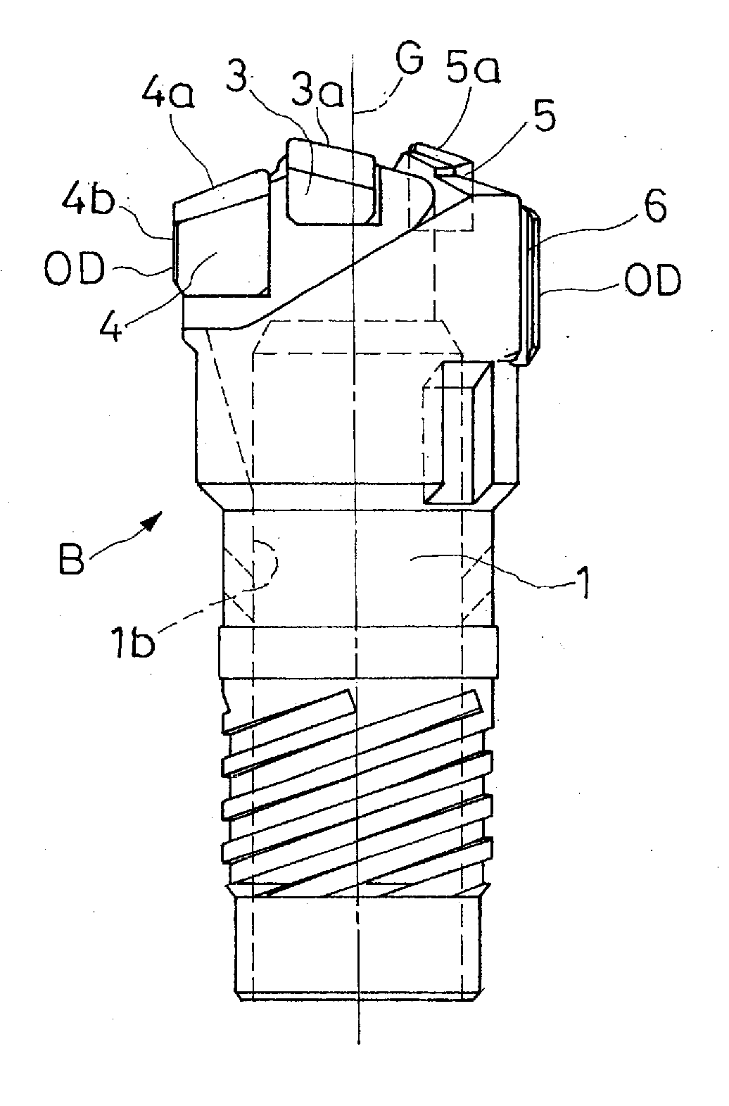
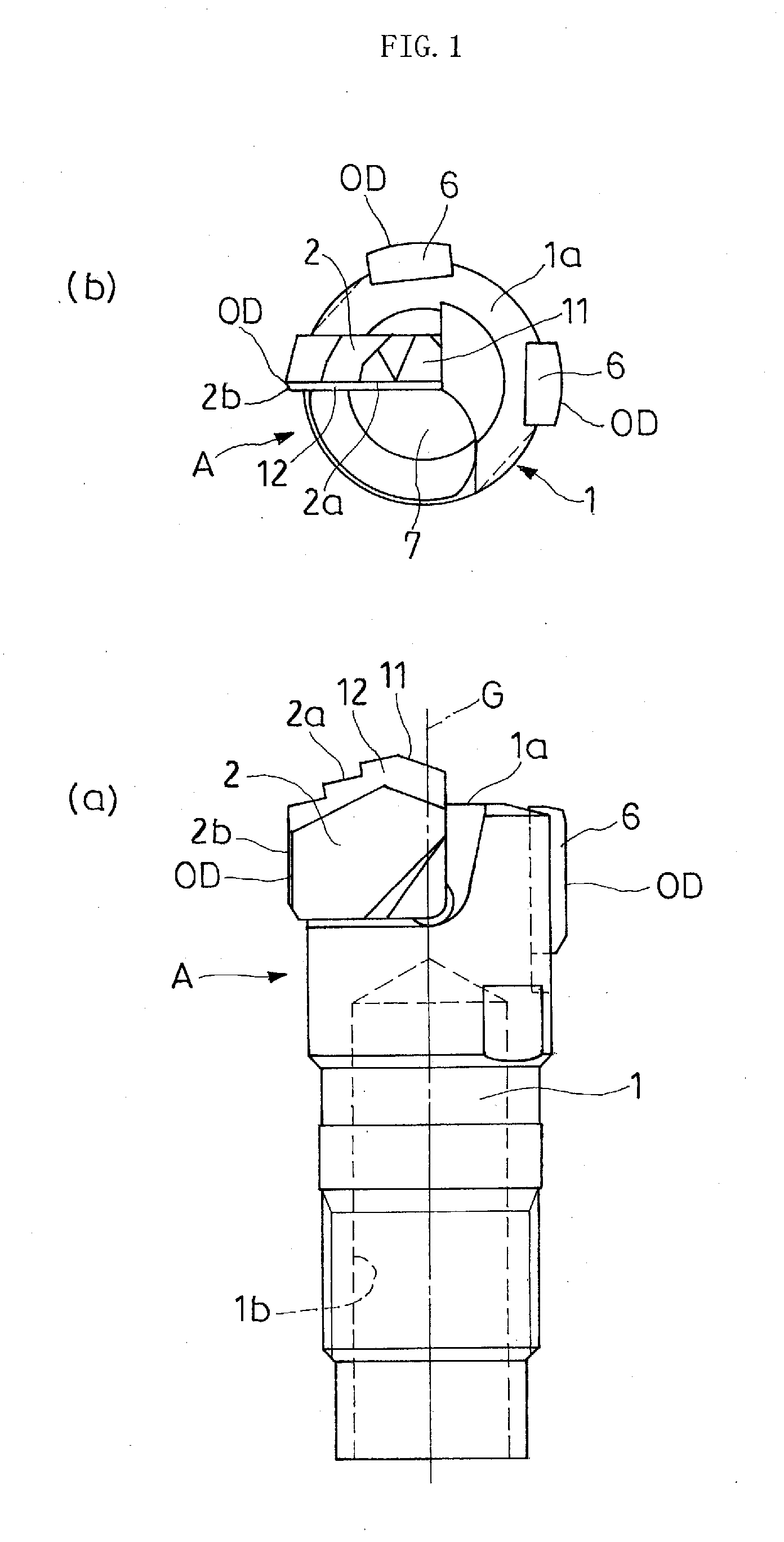
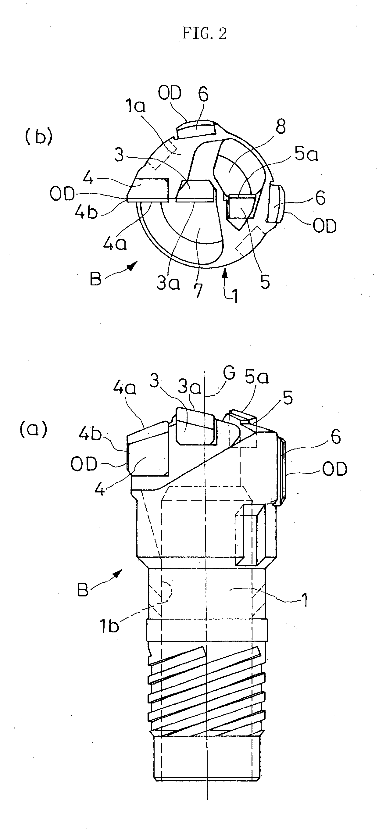
[0026]Preferred embodiments of the present invention will be described with reference to the drawings. FIG. 1(a) is a front view showing a drill head manufactured by a method according to the present invention, and FIG. 1(b) is a plan view thereof. The drill head A has a substantially cylindrical head main body 1. The head main body 1 has a distal end side surface 1a brazed with a piece of cutting tip 2 radially from a rotation axis G thereof. The cutting tip 2, upon brazing, has blade point portions 2a and 2b at a distal end side and an outer circumferential side, respectively. Moreover, guide pads 6 are brazed to predetermined portions on side surfaces of the head main body 1 in the same manner as the cutting tip 2. Reference numeral 7 denotes a chip discharge port communicated with a hollow portion 1b of the head main body 1 in FIG. 1.

[0027]Embodiments of a manufacturing method of the drill head A will now be described.

[0028]First, the cutting tip 2 is CVD coated with a hard mate...


PUM

PropertyMeasurementUnit
thicknessaaaaaaaaaa
ODaaaaaaaaaa
thicknessaaaaaaaaaa

Abstract

A drill head manufacturing method calls for a cutting tip to be CVD coated, brazed to a distal end of a drill head, polished and then PVD coated. The process effectively utilizes features of a CVD coating, which renders a tool service life longer and enables a drill head more suitable for high-speed cutting to be manufactured. A cutting tip having been CVD coated with a hard material is brazed at a brazing temperature to a predetermined portion at a distal end side of a head main body. An outer diameter portion OD of the brazed tip about a rotation axis of the head main body is polished. Then, the cutting tip and the head main body are PVD coated with a hard material at a second temperature lower than the brazing temperature.

Description

RELATED APPLICATIONS[0001]This is a Continuation-in-Part of International Application No. PCT / JP2008 / 072630, filed 12 Dec. 2008 and published as WO 2010 / 007700 on 21 Jan. 2010, which claims priority to JP 2008-184844, filed 16 Jul. 2008. The contents of the aforementioned International and priority applications are incorporated by reference in their entirety.FIELD OF THE INVENTION[0002]The present invention relates to a manufacturing method of a drill head used for drilling a metal workpiece. The present invention further relates to a drill head manufactured by the method.BACKGROUND[0003]In manufacturing a drill head, conventionally, first, a cutting tip and a guide pad are silver brazed at a brazing temperature to predetermined portions at a distal end side of a head main body such that an outer diameter portion of the cutting tip is positioned along an outer circumference of the drill head. Then, outer diameter portions of the brazed cutting tip and guide pad about a rotation axis...

Claims


Application Information

Patent Timeline
21 Jul 2011
Publication
US20110176878A1
IPC
B23B51/00; B23K31/02
CPC
B23B51/0493; B23B2228/04; B23B2228/08; B23B2228/10; Y10T408/5586; C23C16/00; C23C30/005; Y10T408/78
Inventors
NOMURA, TAKUJI