Debris collecting apparatus and methods of making and using the same

a technology of dust collection and dust collection nozzle, which is applied in the direction of chemistry apparatus and processes, manufacturing tools, cleaning equipment, etc., can solve the problems of dust and particles, potential hazards, and generation of debris, and achieve the effect of reducing the risk of dust accumulation and dust accumulation

Active Publication Date: 2011-07-28
HABBOUSH SARMAD J
View PDF4 Cites 6 Cited by
  • Summary
  • Abstract
  • Description
  • Claims
  • Application Information

AI Technical Summary

Problems solved by technology

By their nature, grinding and machining processes necessarily result in the generation of debris, such as dust and particles.
During grinding and machining operations, very fine particles of dust and material may become airborne and alight on surfaces of the surrounding workplace, creating a dust-covered workplace, or creating potential hazards, depending on the nature of the particles.
For example, under certain circumstances, the suspension in air of combustible materials, such as fine sawdust particles, in an enclosed space may create the potential for explosions or other unsafe conditions.
For example, long-term inhalation of dust may cause respiratory injury, such as lung discomfort, allergic reactions in persons with asthma, or other conditions requiring medical treatment.
Furthermore, in some situations, minute particles suspended in the air surrounding a grinding or machining workplace may enter and injure the eyes of persons in the vicinity of the grinding or machining operation.
Such potential health and safety risks may in addition to the increased effort requi

Method used


Image

  • Debris collecting apparatus and methods of making and using the same
  • Debris collecting apparatus and methods of making and using the same
  • Debris collecting apparatus and methods of making and using the same

Examples


Embodiment Construction

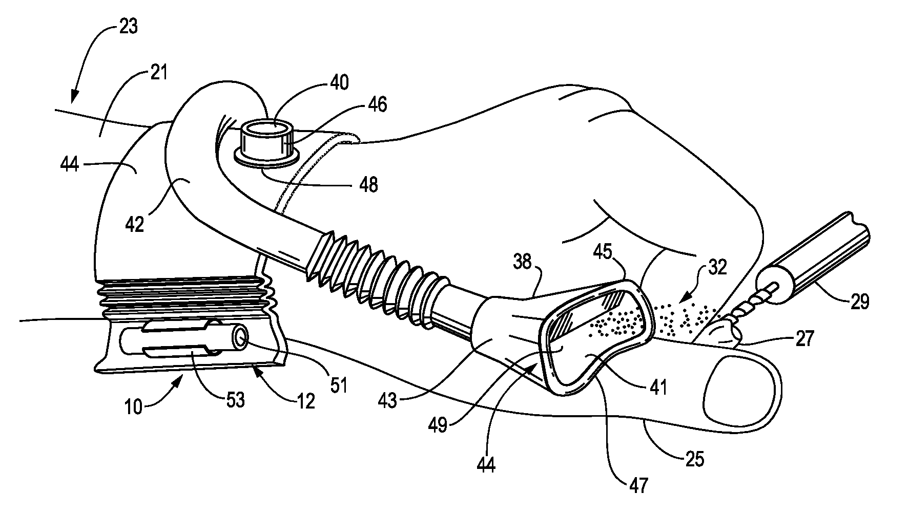
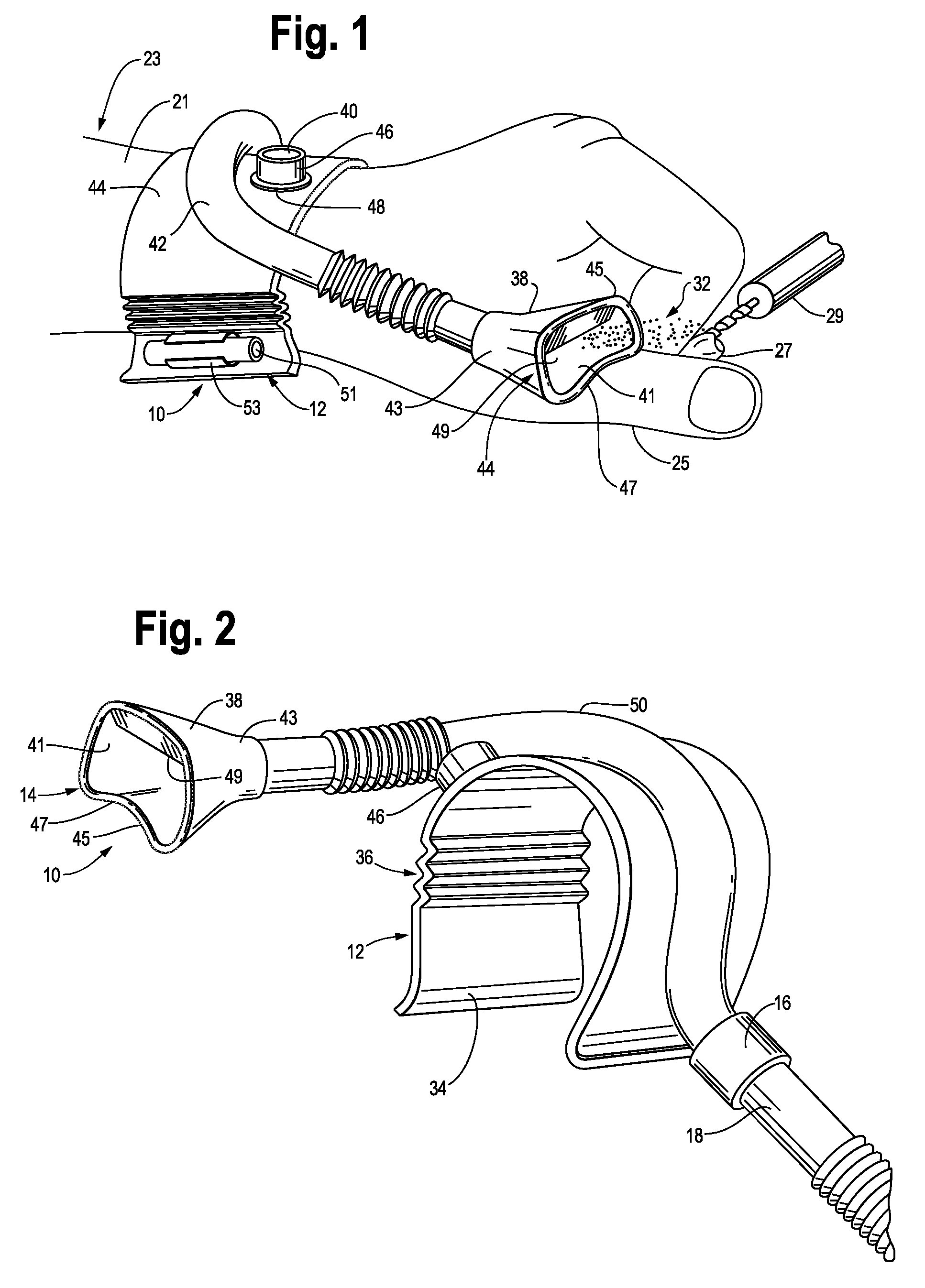
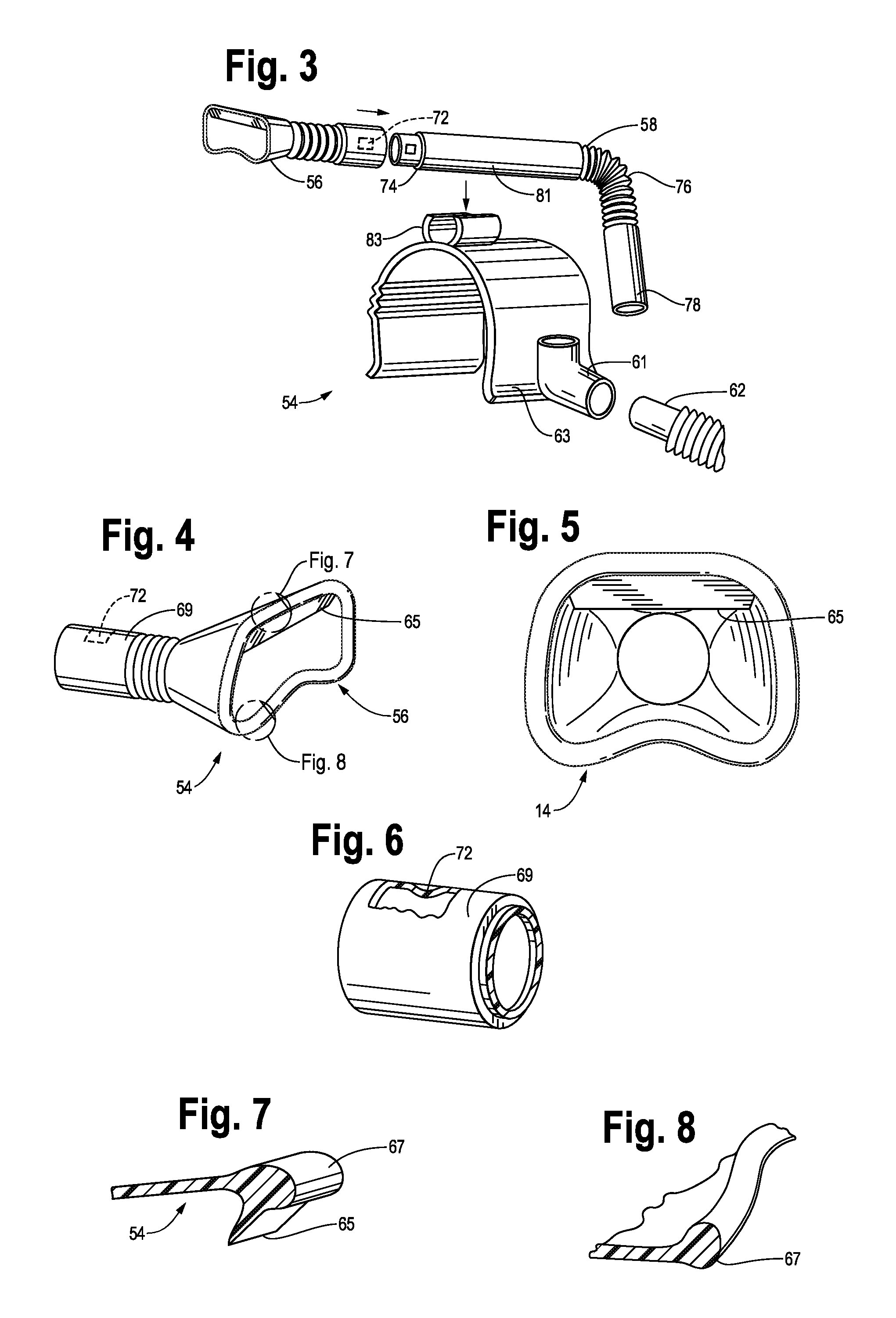
[0031]Certain embodiments of the present invention will now be described more fully hereinafter with reference to the accompanying drawings, in which some, but not all, embodiments of the invention are shown. Indeed, these embodiments of the invention may be in many different forms and thus the invention should not be construed as limited to the embodiments set forth herein; rather, these embodiments are provided as illustrative examples only so that this disclosure will satisfy applicable legal requirements. Like numbers refer to like elements throughout.

[0032]It will be readily understood that the components of the embodiments as generally described and illustrated in the drawings herein, could be arranged and designed in a wide variety of different configurations. Thus, the following more detailed description of the certain embodiments of the system, components and method of the present invention, as represented in the drawings, is not intended to limit the scope of the invention...


PUM

PropertyMeasurementUnit
Flexibilityaaaaaaaaaa
Vacuumaaaaaaaaaa

Abstract

A system and method are disclosed for a suction nozzle for attachment to a vacuum source, such as a suction line, to collect debris such as airborne particles. The suction nozzle includes a tubular-shaped funnel with a large mouth at one end, to receive and channel airborne debris to the vacuum source. The suction nozzle also includes a connector at an opposite end of the funnel, for connecting the suction nozzle to a vacuum source. The mouth of the funnel may further include an inwardly-extending rim portion, which is shaped to accommodate objects that may be adjacent to the funnel and its mouth. The mouth includes a lip extending inwardly from the rim of the mouth for helping deflect debris inwardly into the funnel. In one embodiment, the rim portion of the funnel mouth may further include a scraper portion which extends inwardly from the rim, toward the interior of the funnel mouth. This scraper portion is useful for helping to remove debris from instruments or other.

Description

RELATED APPLICATION[0001]This application claims priority to U.S. Provisional Patent Application Ser. No. 61 / 336,891, filed Jan. 28, 2010 and entitled “Chair side dental dust collector suction adapter,” which is incorporated herein by reference.FIELD OF THE INVENTION[0002]This application generally relates to the field of debris-collecting devices, and, more particularly, to suction nozzles connected to a vacuum source for the collection of debris, such as dust particles and others, produced in, and resulting from, a variety of operations such as grinding and machining operations, as well as the operation of power tools and others.BACKGROUND OF THE INVENTION[0003]There is no admission that the background art disclosed in this section legally constitutes prior art.[0004]As discussed above, this application generally relates to devices for the collection of debris in various environments. This field includes several examples of debris-collecting devices. For instance, U.S. Pat. No. 4,...

Claims


Application Information

Patent Timeline
IPC IPC(8): A47L9/06B23P17/04
CPCB24B55/06Y10T29/49826A47L25/00B08B15/04A47L5/24
Inventor HABBOUSH, SARMAD J.
Owner HABBOUSH SARMAD J
Why Eureka
Try Eureka