Enhanced magnetic self-assembly using integrated micromagnets

Inactive Publication Date: 2011-07-28
UNIV OF FLORIDA RES FOUNDATION INC
View PDF14 Cites 30 Cited by
  • Summary
  • Abstract
  • Description
  • Claims
  • Application Information

AI Technical Summary

Benefits of technology

[0025]Embodiments of the invention relate to a method and system for magnetic self-assembly (MSA) of one or more parts to another part. Assembly occurs when the parts having magnet patterns bond to one another. Such bonding can result in energy minima. The magnetic forces and torques—controlled by the size, shape, material, and magnetization direction of the magnetic patterns cause the components to rotate a

Problems solved by technology
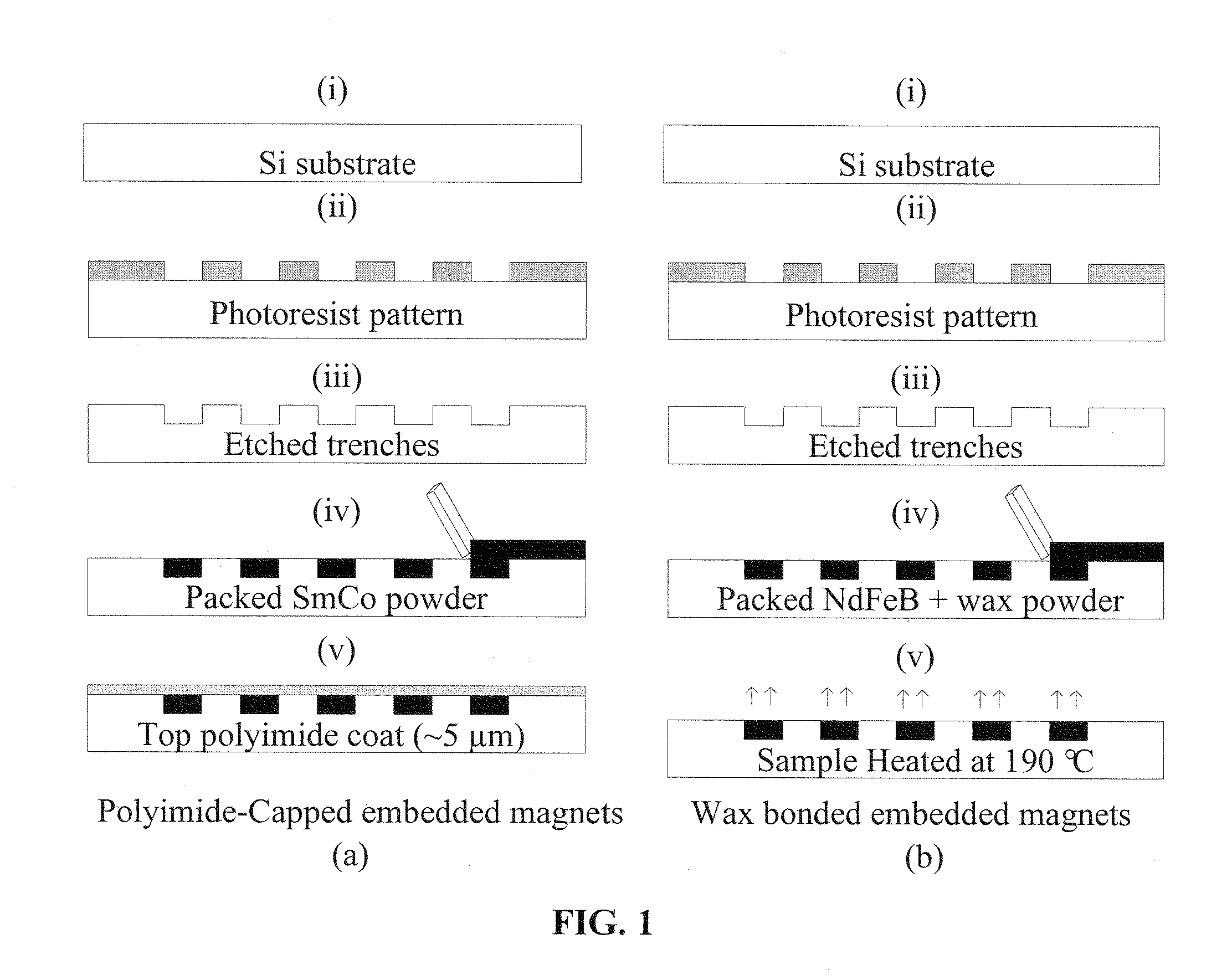
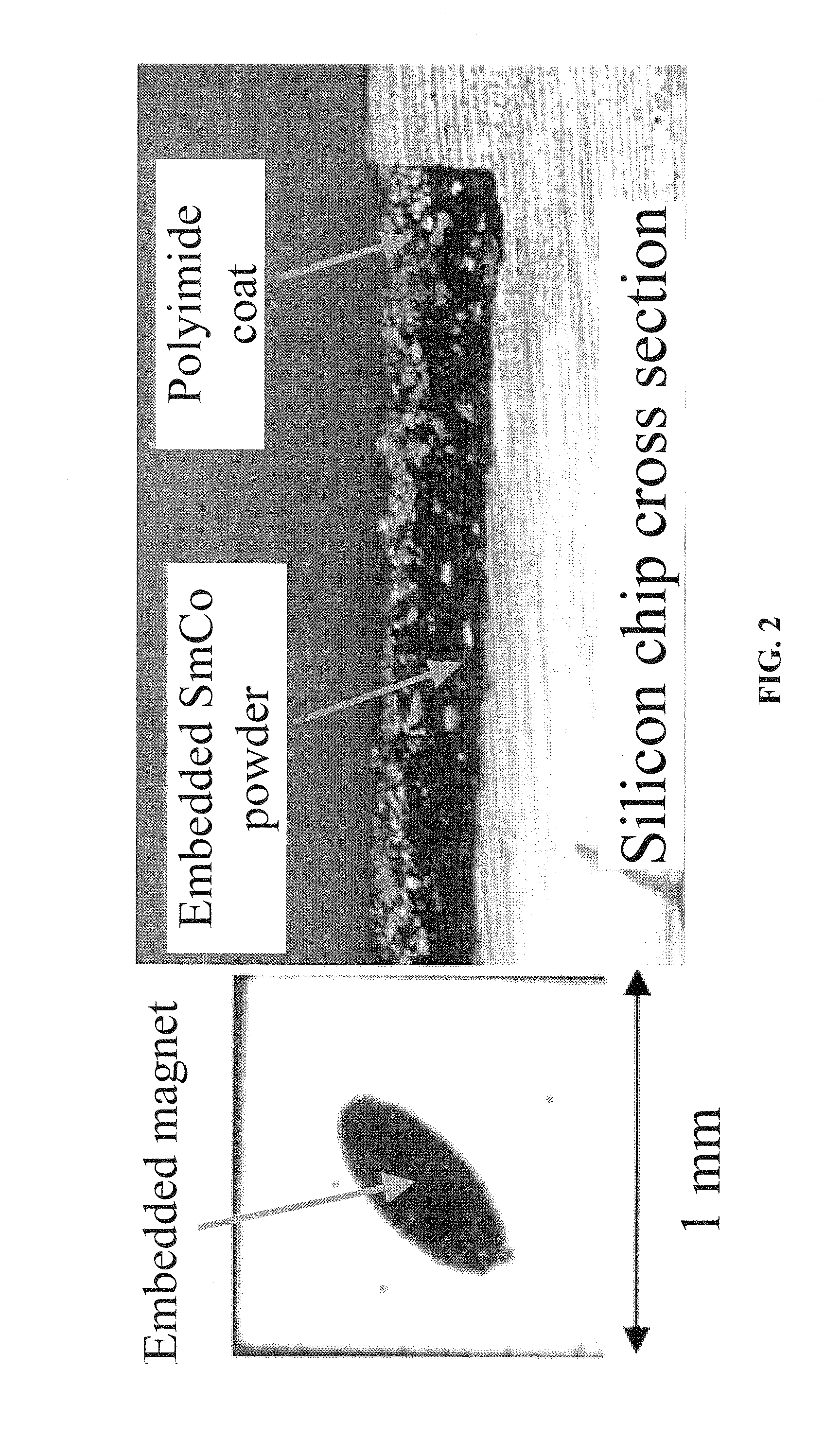
Such bonding can res

Method used


Image

  • Enhanced magnetic self-assembly using integrated micromagnets
  • Enhanced magnetic self-assembly using integrated micromagnets
  • Enhanced magnetic self-assembly using integrated micromagnets

Examples


example 1

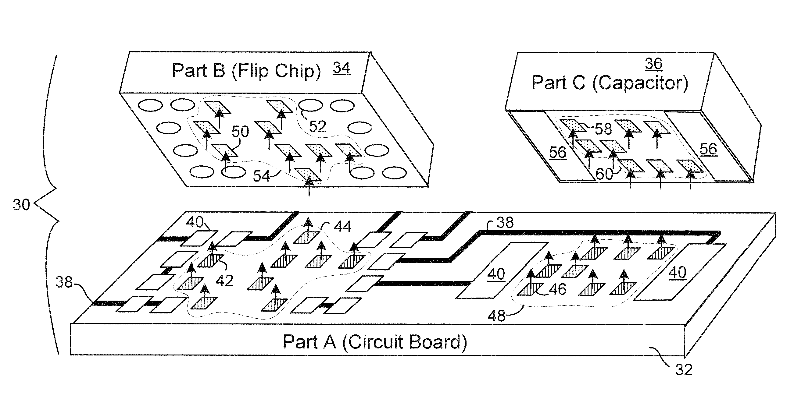
Multifunctional Self-Assembly of Millimeter Scale Components

[0104]The self-assembly of the components in this example use magnetic forces between permanent micromagnets integrated on the component surfaces. Part-to-part assembly is demonstrated by batch assembly of free-floating 1 mm×1 mm×0.5 mm silicon parts in a liquid environment with the assembly yield varying from 88% to 90%. Part-to-substrate assembly is demonstrated by assembling an ordered array on a substrate in a dry environment with the assembly yield varying from 87% to 98%. In both cases, diverse magnetic shapes / patterns are used to control the alignment and angular orientation of the components and assembly times range from 15-240 s.

[0105]In this example, part-to-part MSA in a liquid environment and part-to-substrate assembly in dry environment, both with angular orientation are accomplished. Different magnetic patterns such as squares, stripes, ovals, triangles, and arrow-heads are explored, covering 4-75% of the bond...


PUM

PropertyMeasurementUnit
Timeaaaaaaaaaa
Magnetic fieldaaaaaaaaaa
Sizeaaaaaaaaaa

Abstract

Embodiments of the invention relate to a method and system for magnetic self-assembly (MSA) of one or more parts to another part. Assembly occurs when the parts having magnet patterns bond to one another. Such bonding can result in energy minima The magnetic forces and torques—controlled by the size, shape, material, and magnetization direction of the magnetic patterns cause the components to rotate and align. Specific embodiments of MSA can offer self-assembly features such as angular orientation, where assembly is restricted to one physical orientation; inter-part bonding allowing assembly of free-floating components to one another; assembly of free-floating components to a substrate; and bonding specificity, where assembly is restricted to one type of component when multiple components may be present.

Description

[0001]The subject invention was made with government support under National Science Foundation, Contract No. DMI-0556056. The government has certain rights to this invention.BACKGROUND OF INVENTION[0002]Embodiments of the subject invention are directed to the use of magnetic forces for self-assembly of three-dimensional structures. Specific embodiments relate to the use of magnetic forces for self-assembly of microfabricated devices on a nanoscale, a micron scale, a millimeter scale, and / or a centimeter scale. Further specific embodiments pertain to the use of magnetic forces for self-assembly of three-dimensional structures for integrated circuits utilizing shaped magnetic fields.[0003]Over the past few decades, advances in the field of electronic and photonic devices for signal processing wireless communication, computing and the like have become more complex as they become more highly integrated. Most systems are an amalgam of heavily integrated microsystems. These systems are en...

Claims


Application Information

Patent Timeline
IPC IPC(8): H05K13/00
CPCH01L24/95Y10T29/5313H01L2924/01013H01L2924/01082H05K3/3436H05K13/0452H05K2203/048H05K2203/104H01L2924/01005H01L2924/01006H01L2924/01033H01L2924/01072H01L2924/01078H01L2924/014H01L2924/1461H01L2224/95085Y10T29/49117H01L2924/00H01L2924/14Y02P70/50
Inventor ARNOLD, DAVID PATRICKSHETYE, SHEETAL BHALCHANDRA
Owner UNIV OF FLORIDA RES FOUNDATION INC
Why Eureka
Try Eureka