Automatic flange surface machining apparatus

a technology of automatic machining and flange surface, which is applied in the direction of chain saws, manufacturing tools, tube shearing machines, etc., can solve the problems of inability to achieve more precise control, increase the weight increase the size of the whole apparatus, so as to reduce the size and weight of the apparatus, the effect of uniform serration, and accurate position and rotation speed

Inactive Publication Date: 2011-07-28
AHN SANG GULK +1
View PDF8 Cites 8 Cited by
  • Summary
  • Abstract
  • Description
  • Claims
  • Application Information

AI Technical Summary

Benefits of technology

[0011]In the automatic flange surface-machining apparatus constructed as above according to the present invention, the bite for machining serration on the flange surface is horizontally moved in the main body and rotated and is driven up-downward according to depth of the serration, therefore uniform roughness of the serration can be obtained, and the serration can be machined with accurate position and rotational speed by connecting the controller to each of the driving parts, and the whole size and weight of the apparatus can be reduced by performing horizontal, up-downward and rotational movement by means of motors.

Problems solved by technology

However, such a prior serration-machining apparatus is pneumatically driven, therefore in addition to a main body of the serration-machining apparatus, a compressor for supplying air pressure to the main body of the serration-machining apparatus is indispensably needed, and weight of the whole apparatus is increased and its size becomes excessively large due to need for the compressor.
Furthermore, the prior serration-machining apparatus has a disadvantage that since the bite is rotated in one direction when the serration is machined and the rotational speed is controlled through pneumatic pressure and the number of stages of the gears mounted in the main body, more precise control is not possible.
The above-mentioned fact causes a problem that roughness (roughness degree of a surface) of the serration machined can not be uniform.
In addition, another problem is present that since the compressor generates pneumatic pressure which is not uniform, vibration is generated in the rotated bite due to un-uniformity of the pneumatic pressure, accordingly the bite is moved, thus the roughness of the serration becomes un-uniform.

Method used


Image

  • Automatic flange surface machining apparatus
  • Automatic flange surface machining apparatus
  • Automatic flange surface machining apparatus

Examples


Embodiment Construction

[0043]Hereinbelow, preferred examples of the automatic flange surface-machining apparatus according to the present invention will be described with reference to the attached drawings. In this regard, thickness of lines or size of constituents etc. illustrated in the drawings may be illustrated by exaggeration for the sake of clarity and convenience of explanation.

[0044]Furthermore, the following examples do not limit the scope of claims of the present invention, rather are only exemplary items of the constituents presented in the claims of the present invention, and within the scope of the claims are also included examples which are included in technical concepts shown in the whole specification of the present invention and comprise constituents which can be substituted as equivalents of the constituents in the claims.

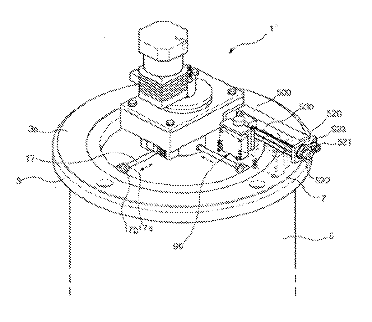
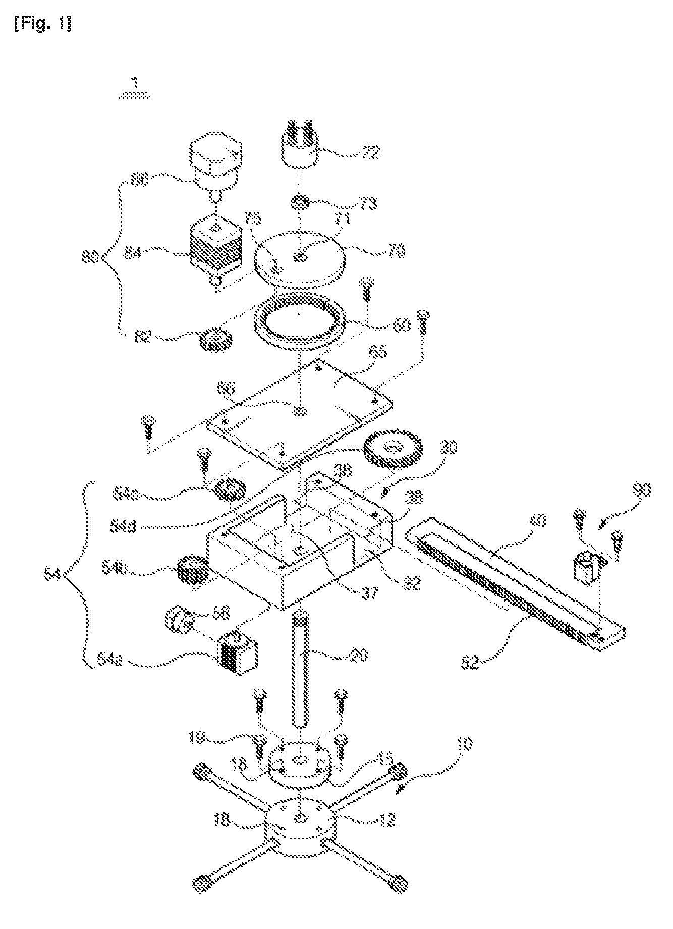
[0045]FIG. 1 is a exploded perspective view illustrating an automatic flange surface-machining apparatus (1) according to a preferred example of the present invention,...


PUM

PropertyMeasurementUnit
poweraaaaaaaaaa
rotational forceaaaaaaaaaa
heightaaaaaaaaaa

Abstract

Disclosed is an automatic flange surface machining apparatus for machining a flange surface. The automatic flange surface machining apparatus of the present invention comprises a flange fixing unit fixed at the inner surface of a pipe formed on a flange, a shaft secured onto the flange fixing unit, a main body which has a linear toolbar guiding path formed at one side thereof, and which has a guide protrusion for providing a space that communicates with the toolbar guiding path to enable the penetration of the shaft, and which is rotatably coupled to the shaft that has penetrated the space, a toolbar installed in the toolbar guiding path such that the toolbar moves along the toolbar guiding path, a toolbar moving means arranged in the main body to move the toolbar, an inner gear coupled onto the main body, a rotating motor base installed on the inner gear, and fixed at the shaft, an inner gear driving means coupled to the rotating motor base to rotate the inner gear, and a flange surface machining unit installed on one side of the toolbar to machine the flange surface.

Description

TECHNICAL FIELD[0001]The present invention relates to an automatic flange surface-machining apparatus, in particular, an automatic flange surface-machining apparatus which can machine flange surface using driving means such as motors and the like.BACKGROUND ART[0002]The flange needs to be serration-machined on its surface contacting with gasket according to the environment in which the flange is used, and in such a maching work of a prior art, the serration is machined by fixing a chuck in a pipe and the like formed with the flange and using a cutting device equipped with a bite rotated around a center of the chuck by means of air pressure over the chuck.[0003]Furthermore, in such a device, the distance from the center of the chuck to the bite is manually adjusted using several gears.[0004]However, such a prior serration-machining apparatus is pneumatically driven, therefore in addition to a main body of the serration-machining apparatus, a compressor for supplying air pressure to t...

Claims


Application Information

Patent Timeline
Patent Type & Authority Applications(United States)
IPC IPC(8): B23D21/00
CPCB23B3/265B23B5/162B26D3/166Y10T83/68B26D1/06B23B5/16
Inventor AHN, SANG GULKLEE, SEONG WON
Owner AHN SANG GULK
Why Eureka
Try Eureka