Drill ship for deep sea intervention operations

a deep sea intervention and drilling vessel technology, applied in the direction of fluid removal, pipe-laying vessels, floating buildings, etc., can solve the problems of damage to stability regulations, ship exceeds the mobile offshore drilling unit passenger vessel intact, etc., and achieves low fuel consumption

a deep sea intervention and drilling vessel technology, applied in the direction of fluid removal, pipe-laying vessels, floating buildings, etc., can solve the problems of damage to stability regulations, ship exceeds the mobile offshore drilling unit passenger vessel intact, etc., and achieves low fuel consumption

US20110180266A1Inactive Publication Date: 2011-07-28A P MOLLER AS

Image

  • Drill ship for deep sea intervention operations
  • Drill ship for deep sea intervention operations
  • Drill ship for deep sea intervention operations

Examples


Embodiment Construction

Hull and Main Ship Design

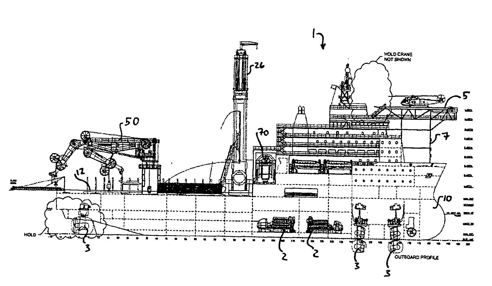
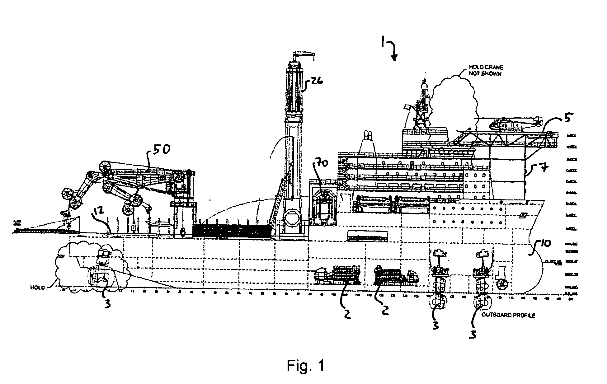
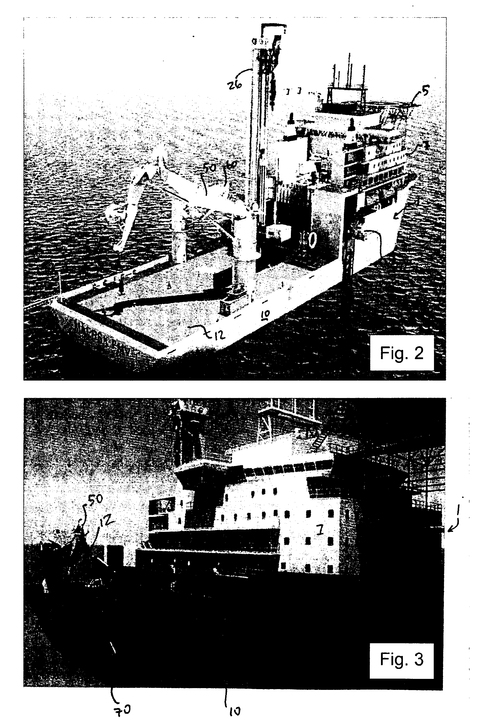
[0034]As shown in FIGS. 1-6, the drill ship 1 includes a hull 10, crew quarters structure at section 7, a helipad 5 and a main deck 12. Positioned on the aft region of the deck 12 are the box tower hoisting and lowering system and top drive 26, a heavy-lift knuckle-boom seafloor active heave crane 50, a medium duty seafloor and deck crane 60, and an ROV installation with an integrated vessel control center 70.

[0035]As shown in FIG. 1, directional thrusters 3 are positioned at various points in the hull, and the engines and power systems are housed within the hull as shown at 2. 4 azimuthing & 1 tunnel variable frequency thrusters are used. (20.3 MW combined thrusters rating), and capability to allow for loss of 1 Thruster in a Worst Case Compartment or Component Failure Mode which complies with requirements for redundant dynamic positioning capability.

[0036]The main hull 10 of the drill ship 1 is shown in the drawings at FIGS. 1-6. The hull 10 is formed for ...


PUM


Abstract

A drill ship is provided for conducting subsea operations, including intervention, maintenance and workover operations. The ship includes a hull having a substantially wide beam-to-length ratio and a deckspace. An automated system for handling tubulars and risers is mounted to the deck space, along with a pipe racking system. The deckspace includes a heavy-lift heave crane for handling seafloor operations and a medium duty crane mounted over the deckspace. The ship is configured to provide heavy lift subsea construction operations including 16-inch riser well intervention and workover programs, connected riser completion operations, and riserless tophole drilling and casing operations. The ship is also able to perform connected riser remedial drilling and slim hole well construction. The ship maximizes environmental efficiency in both construction and use, and provides a stable and safe work and living environment for operations personnel.

Description

SUMMARY OF THE INVENTION[0001]In one embodiment, the drill ship is configured to operate in multi-tasking environments for subsea oil and gas field development and maintenance, including various subsea operations up to 7,500 feet of water depth. The drill ship includes capabilities for connected 16″ riser well intervention and work over programs, heavy lift subsea construction programs, connected 16″ riser small outer diameter tubing hanger completion programs, riserless tophole large outer-diameter drilling and casing batch programs, and connected riser remedial drilling and slim hole well construction.[0002]The design of the drill ship incorporates elements to ensure safety of personnel and environmentally efficient and “green” operation and construction. In particular, the ship exceeds the Mobile Offshore Drilling Unit (MODU) Passenger Vessel Intact and Damage Stability regulations. The design also incorporates concepts for protected temporary safe refuge muster concepts. Provisi...

Claims


Application Information

Patent Timeline
28 Jul 2011
Publication
US20110180266A1
IPC
E21B43/01; B63B35/44; B63B35/50; E21B33/06
CPC
B63B35/03; E21B7/02; B63B35/4413
Inventors
ELMBO, NIELS; DANIELSEN, THOMAS