Power management DC-DC converter and method for induction energy harvester

Active Publication Date: 2011-07-28
TEXAS INSTR INC
View PDF2 Cites 65 Cited by
  • Summary
  • Abstract
  • Description
  • Claims
  • Application Information

AI Technical Summary

Benefits of technology

[0016]It is an object of the invention to provide a way to avoid the high cost of the coil or inductor usually r

Problems solved by technology

Consequently, at low vibration levels it may take several minutes before there is sufficient energy to acquire a vibration spectra and transmit it.
Another shortcoming is that it does

Method used


Image

  • Power management DC-DC converter and method for induction energy harvester
  • Power management DC-DC converter and method for induction energy harvester
  • Power management DC-DC converter and method for induction energy harvester

Examples


Embodiment Construction

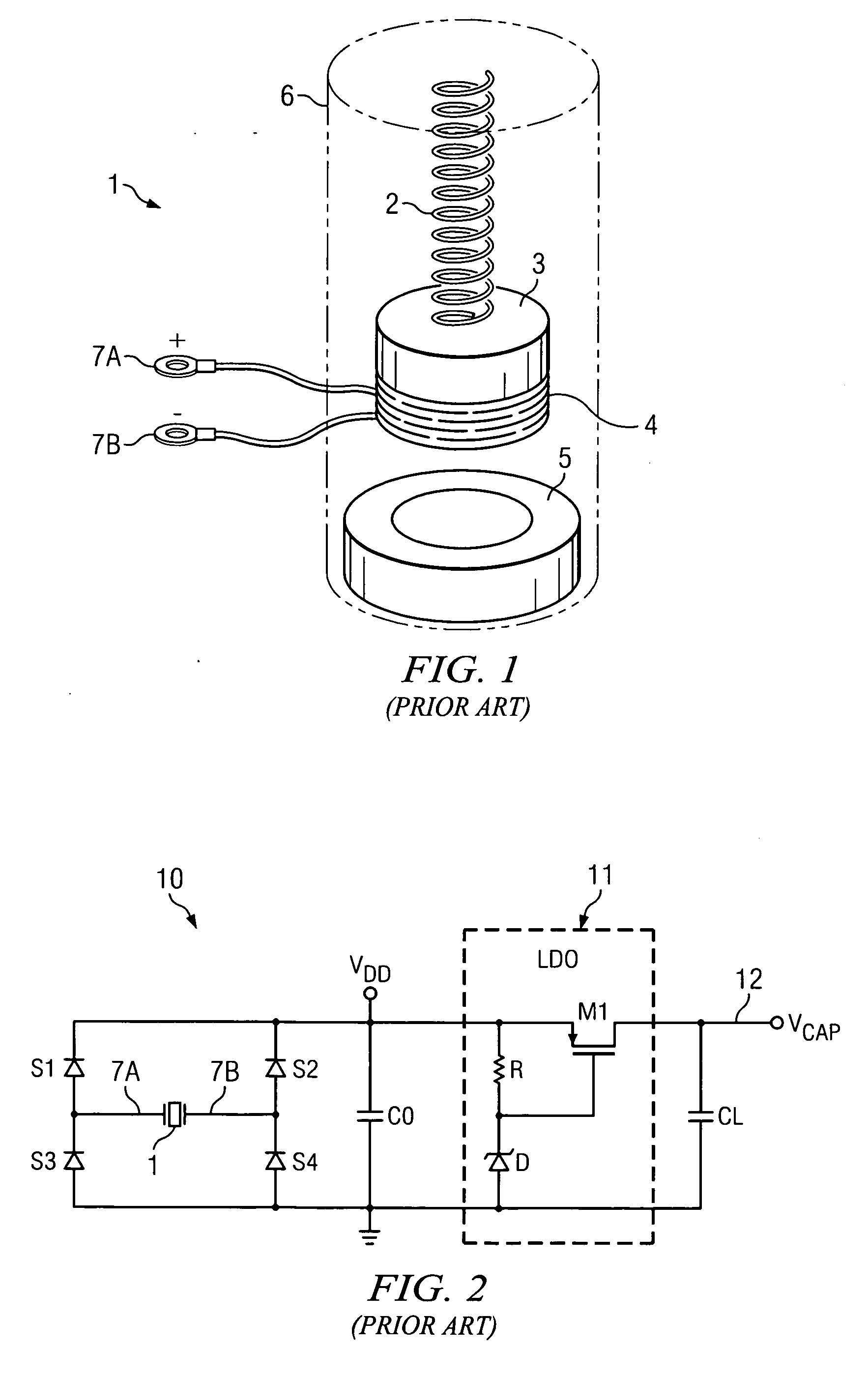
r management circuit for an induction harvester as shown in FIG. 1.

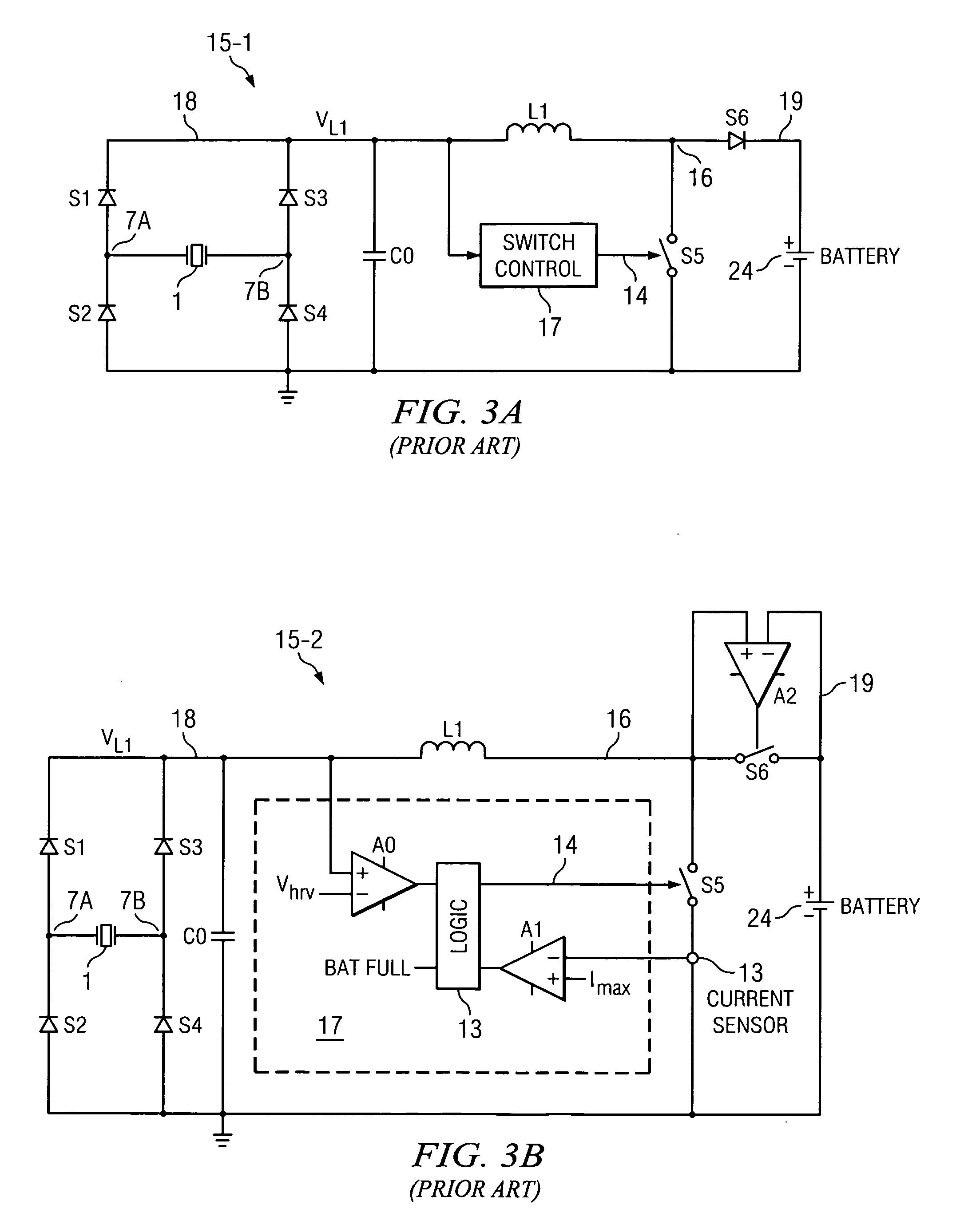
[0035]FIG. 3A is a simplified schematic diagram of a prior art power management circuit including a vibration micro harvester and a boost converter.

[0036]FIG. 3B is a more detailed schematic diagram of the prior art power management circuit in FIG. 3A.

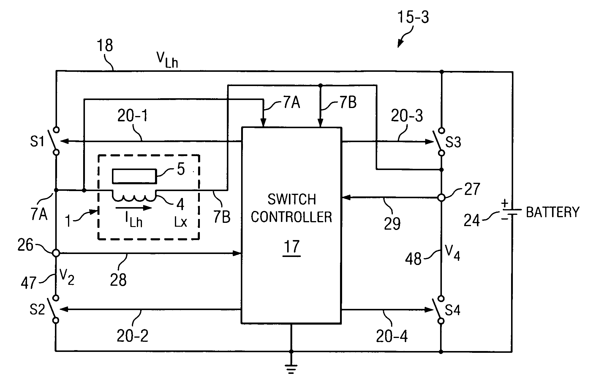
[0037]FIG. 4A is a block diagram of an inductive harvested power management circuit of the present invention.

[0038]FIG. 4B is a schematic diagram of the inductive harvester power management circuit of FIG. 4A.

[0039]FIG. 4C is a graph useful in explaining the operation of the circuit shown in FIG. 4B.

[0040]FIG. 5A is a schematic diagram of another inductive harvester power management circuit of the present invention.

[0041]FIG. 5B is a graph useful in explaining the operation of the circuit shown in FIG. 5A.

DETAILED DESCRIPTION OF THE PREFERRED EMBODIMENTS

[0042]The first two previously mentioned problems of the system of Prior Art FIGS. 3A and 3B (i.e., the requirement of...


PUM

PropertyMeasurementUnit
Frequencyaaaaaaaaaa
Electrical resistanceaaaaaaaaaa
Currentaaaaaaaaaa

Abstract

A system for managing AC energy harvested from a harvesting device (1) including a coil (4) including switching circuitry (S1-S4) coupled between first (7A) and second (7B) terminals of the coil. The switching circuitry includes first (S1), second (S2), third (S1), and fourth (S4) switches. A switch controller (17) closes the second and fourth switches to allow build-up of current (ILh) in the coil, opens one of the second and fourth switches, and closes a corresponding one of the third and first switches in response to the built-up inductor current reaching a predetermined threshold value (Ihrv) to steer the built-up inductor current through the corresponding one of the third and first switches to a current-receiving device (24 and/or RL,CL).

Description

BACKGROUND OF THE INVENTION[0001]The present invention relates generally to use of induction type energy harvesters along with DC-DC converters, and more particularly to switching circuitry and techniques for using the inductance of the energy harvester both for inductive energy harvesting and for performing DC-DC conversion of the energy harvester output.[0002]The basic structure of an induction type vibration energy harvester 1 is shown in FIG. 1. It includes a mass m and associated coil or inductor 4 suspended on one end of a spring 2. The mass m and coil 4 move with velocity v relative to a magnet 5. The other end of spring 2 and magnet 5 are supported by a support 6. (The coil might be stationary with the magnet moving, or vice versa.). When coil 4 and associated mass m move with velocity v in the magnetic field, their kinetic energy Ek=(mv2) / 2 is transformed into potential energy in spring 2 which then is converted into electromagnetic energy ELh=eL=(LhILh2) / 2. The electromoti...

Claims


Application Information

Patent Timeline
IPC IPC(8): H02M3/335H02M7/217
CPCH02M7/219
Inventor IVANOV, VADIM V.
Owner TEXAS INSTR INC
Why Eureka
Try Eureka