Electric actuator including two current-controlled voltage inverters powering an electric machine, and reconfigurable in the presence of a defect

a voltage inverter and electric actuator technology, applied in the field of aviation, can solve the problems of significant complexity of control, and the inability to control the passing through the arm that remains sound,

Active Publication Date: 2011-07-28
SAFRAN LANDING SYSTEMS +2
View PDF7 Cites 36 Cited by
  • Summary
  • Abstract
  • Description
  • Claims
  • Application Information

AI Technical Summary

Benefits of technology

[0015]The controlled connection means enable an inverter to be completely isolated from the power supply network(s) so as to put th

Problems solved by technology

Nevertheless, that type of inverter has arms, each of which includes two control switches or transistors that may become blocked in an open state or in a closed state.
When one of the

Method used


Image

  • Electric actuator including two current-controlled voltage inverters powering an electric machine, and reconfigurable in the presence of a defect
  • Electric actuator including two current-controlled voltage inverters powering an electric machine, and reconfigurable in the presence of a defect
  • Electric actuator including two current-controlled voltage inverters powering an electric machine, and reconfigurable in the presence of a defect

Examples


second embodiment

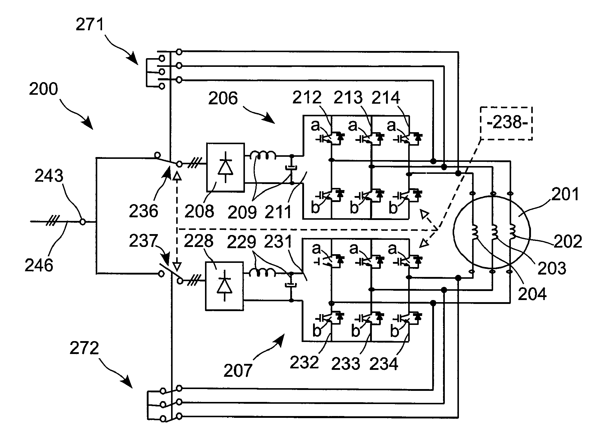
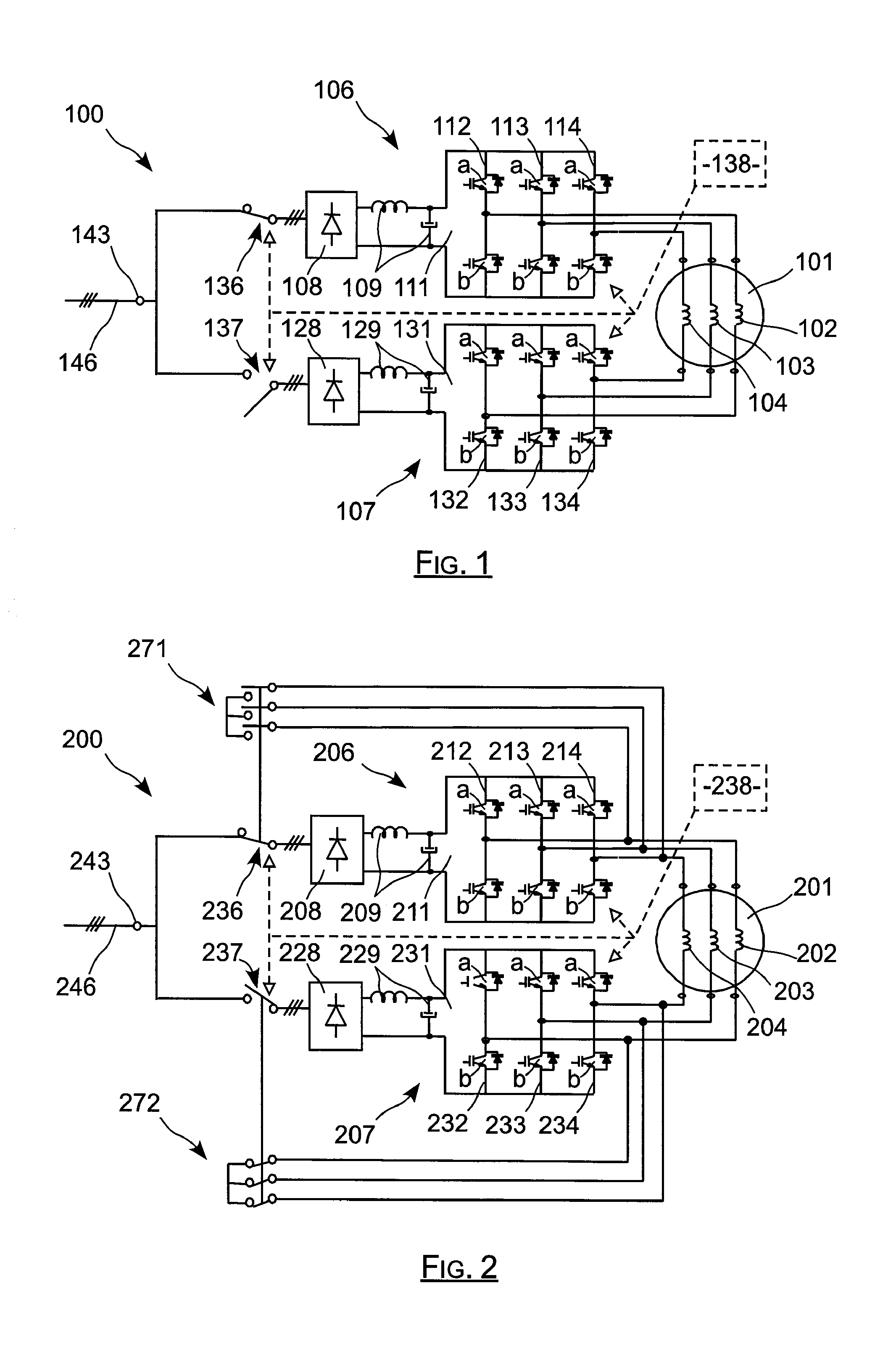
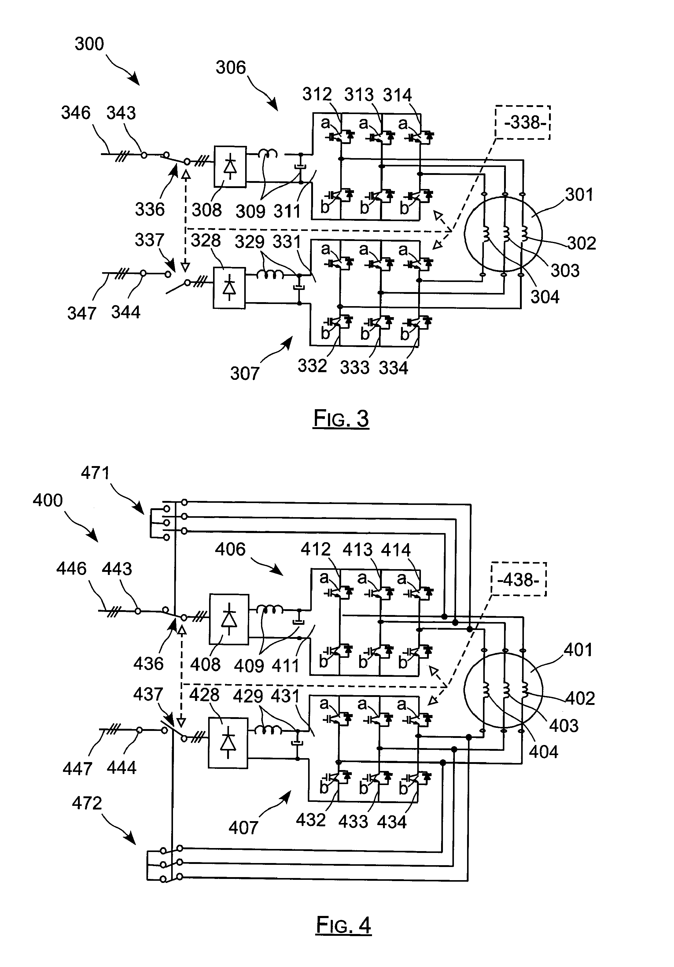
[0063]In a second embodiment, the actuator as shown in FIG. 3 under the reference 300 is powered by two distinct three-phase electrical networks. This actuator 300 has all of the members of the actuator 100 of FIG. 1, these members carrying numerical references corresponding to those of the actuator 100 plus two hundred.

[0064]The actuator 300 has two inlet connection members referenced 343 and 344 that are situated respectively in register with its first bus 306 and with its second bus 307, which members are connected respectively to first and second three-phase electrical power supply networks referenced 346 and 347.

[0065]The first contactor 336 connects the rectifier 308 of the first bus 306 to the first connection member 343, while the second contactor 337 connects the rectifier 328 of the second bus 307 to the second connection member 344. The first bus 306 is thus powered by the first three-phase electrical network 346, and the second bus 307 is powered by the second three-phas...

third embodiment

[0070]In the invention, the actuator is powered by first and second three-phase electrical networks, while also including means enabling each of its two buses to be powered either by one or by the other one of these networks.

[0071]This actuator 500 is shown in FIG. 5 and has general structure of the same type as the actuator 300 of FIG. 3. It has all of the members of the actuator 300 of FIG. 3, these members being given numerical references that correspond to those of the actuator 300, plus two hundred.

[0072]This other actuator has two inlet connection members 543 and 544 that are connected to respective ones of the two three-phase networks 546 and 547. The two contactors 536 and 537 that are connected respectively to the first and second rectifiers are connected to the two connection members 543 and 544 via a changeover switch having two additional positions, the switch being referenced 539 and being controlled by the control unit 538. This switch 539 is advantageously a contactor...

fourth embodiment

[0083]In a fourth embodiment corresponding to the actuator 700 of FIG. 7, the actuator is powered by first and second three-phase electrical networks, while including two three-position switches enabling each of its two inverters to be powered by one or the other of these networks.

[0084]This actuator 700 presents a general structure of the same type as the actuator 300 of FIG. 3. This actuator 700 has all of the members of the actuator 300 of FIG. 3, these members being given numerical references corresponding to those of the actuator 300, plus four hundred. Nevertheless, the first and second contactors, referenced 736 and 737 in this embodiment, are switches that have three positions, instead of being simple on / off switches as in the actuator 300. These components 736 and 737 are advantageously contactors of the 3PDTCO type.

[0085]As shown in FIG. 7, this switch may occupy a first position in which it connects the first contactor 736 to the first connection member 743. It may occupy...


PUM


Abstract

The invention relates to an actuator including an electrical machine. The electrical actuator (100) comprising: a polyphase machine (101); at least one connection member (143) for powering the actuator from at least one network (146) delivering alternating current; and first and second buses (106, 107) connected in parallel between each connection member (143) and the machine (101) for applying frequency control thereto. Each inverter (111, 131) comprises a plurality of arms each having two controlled switches, each phase of the machine (101) being connected both to the two switches of an arm of the first inverter (111) and also to the two switches of an arm of the second inverter (131). The actuator further comprises controlled connection and disconnection means interposed between each bus (106, 107) and each connection member. The invention is applicable to actuators used in aviation.

Description

[0001]The invention relates to an electrical actuator for fitting to an aircraft in order to control a piece of equipment of said aircraft.BACKGROUND OF THE INVENTION[0002]In the field of aviation, it is expected that a system for controlling a piece of equipment will be available continuously. This means that in the event of a failure of any component in the system, the control system must be capable of operating, e.g. in a “limp-home” mode, so as to operate the equipment in spite of the failure. Thus, when a failure is detected in flight, the system can continue to operate.[0003]In this context, the control systems actually in use in the field of aviation are hydraulic: they comprise a hydraulic actuator of the cylinder type, and a hydraulic network interposed between the cylinder and a control member.[0004]The network then has two hydraulic circuits that are distinct and independent: in the event of either circuit failing, e.g. as a result of a leak, the other circuit remains ava...

Claims


Application Information

Patent Timeline
IPC IPC(8): H02P6/14
CPCH02M7/49H02M7/493H02P6/085H02P27/06H02P29/02H02M7/53873
Inventor LIEGEOIS, PIERRE-YVESLEYNAERT, FRANCOIS-NOELMEIBODY-TABAR, FARIDPIERFEDERICI, SERGE LIONELNAHID MOBARAKEH, BABAK
Owner SAFRAN LANDING SYSTEMS
Why Eureka
Try Eureka