Guide thimble plug for nuclear fuel assembly

a technology for nuclear fuel and assembly, which is applied in the direction of nuclear elements, vehicle sub-unit features, and greenhouse gas reduction, etc., can solve the problems of reducing product quality, reducing productivity, and difficult assembly of shock absorption tubes and guide thimbles, so as to reduce the thermal strain of the guide thimbles and improve the efficiency of nuclear fuel assembly assembly and manufacturing.

Active Publication Date: 2011-07-28
KEPCO NUCLEAR FUEL CO LTD
View PDF23 Cites 14 Cited by
  • Summary
  • Abstract
  • Description
  • Claims
  • Application Information

AI Technical Summary

Benefits of technology

[0020]In the present invention, a shock absorption tube and a guide thimble can be reliably coupled to a bottom nozzle using a single guide thimble plug. Furthermore, thermal strain of the guide thimble can be minimized when welding for coupling the guide thimble plug to the guide thimble. Hence, the efficiency with which the nuclear fuel assembly is assembled and manufactured can be markedly enhanced.

Problems solved by technology

However, in conventional techniques, when a single guide thimble plug is welded to the double tube structure, a welded portion may be deformed, resulting in the assembly of the shock absorption tube and the guide thimble being very difficult.
Therefore, the quality of the product is diminished.
As a result, when the guide thimble is assembled with other elements of the nuclear fuel assembly, a large load is applied to the nuclear fuel assembly, thus reducing the productivity, and reducing the quality of the product.
That is, when the upper end of the guide thimble plug is coupled to the shock absorption tube 7, if welding is used as a means for coupling, the straightness of the guide thimble and the shock absorption tube can be compromised, or a welded portion of the shock absorption tube is expanded in diameter so that it becomes very difficult to insert the shock absorption tube into the guide thimble.
Furthermore, if the guide thimble plug is coupled to the shock absorption tube by force-fitting, when the guide thimble plug is welded to the guide thimble, the shock absorption tube may be undesirably loosened or removed from the guide thimble plug by welding heat.

Method used


Image

  • Guide thimble plug for nuclear fuel assembly
  • Guide thimble plug for nuclear fuel assembly
  • Guide thimble plug for nuclear fuel assembly

Examples


first embodiment

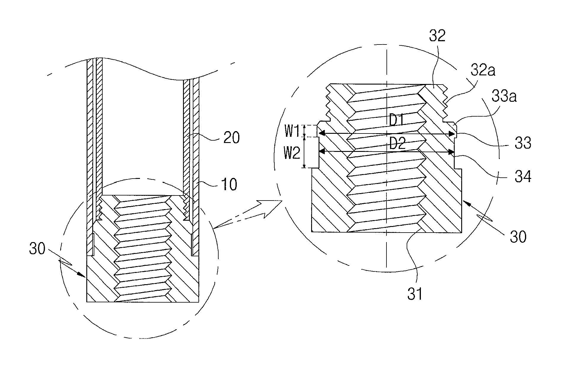
[0029]FIG. 4 is a sectional view illustrating a guide thimble plug for a nuclear fuel assembly according to the present invention.

[0030]As shown in FIG. 4, the guide thimble plug 30 according to the first embodiment has an approximately cylindrical main body. The guide thimble plug 30 has an upper insert part 32 which is provided on the upper end of the cylindrical main body and is tightened into a shock absorption tube 20, and a thermal deformation prevention part 34 which is recessed from the circumferential outer surface of the approximate medial portion of the guide thimble plug 30, such that a gap is defined between the thermal deformation prevention part 34 and the inner surface of a guide thimble 10 when the guide thimble plug 30 is fitted into the guide thimble 10.

[0031]An internal threaded hole 31 is formed through the guide thimble plug 30 so that a bottom nozzle is coupled to the guide thimble plug 30 by screw coupling. An external thread 32a is formed on the circumferent...

second embodiment

[0035]FIG. 5 is a sectional view illustrating a guide thimble plug for a nuclear fuel assembly according to the present invention.

[0036]As shown in FIG. 5, the second embodiment shows another example of the coupling of the guide thimble plug to the shock absorption tube. The guide thimble plug 40 according to the second embodiment includes an internal threaded hole 41, an upper insert part 42, a protruding part 43, a chamfered surface 43a and a thermal deformation prevention part 44, in the same manner as that of the first embodiment.

[0037]However, unlike the first embodiment in which the external thread 32a is formed on the circumferential outer surface of the upper insert part 32, in the second embodiment, a caulking groove 42a is formed in a circumferential direction on the outer surface of the upper insert part 42 of the guide thimble plug 40 which is fitted into a shock absorption tube 20.

[0038]After the upper insert part 42 of the guide thimble plug 40 is inserted into the sho...

third embodiment

[0039]FIG. 6 illustrates a guide thimble plug 50 according to the present invention.

[0040]As shown in FIG. 6, the guide thimble plug 50 according to the third embodiment includes an internal threaded hole 41, an upper insert part 42, a protruding part 43, a chamfered surface 43a and a thermal deformation prevention part 44 in the same manner as the guide thimble plug 40 of the second embodiment.

[0041]In the case of the third embodiment, caulking depressions 52a are formed on the outer circumference of the upper insert part 42 at positions spaced apart from each other at predetermined intervals with respect to the circumferential direction, unlike the second embodiment in which the caulking groove 42a is formed in the circumferential direction on the outer surface of the upper insert part 42. Caulking groove indicators 53a are formed in the upper surface of the protruding part 43 at positions corresponding to the lower ends of the relative caulking depressions 52a. Due to the caulkin...


PUM


Abstract

A guide thimble plug for a nuclear fuel assembly is provided, in which an internal threaded hole is formed through a main body so that the main body is coupled to a bottom nozzle by a screw coupling. An upper insert part is formed in the upper end of the main body. The upper insert part is inserted into a shock absorption tube. A thermal deformation prevention part is formed on the main body below the upper insert part and is recessed inward from the outer surface of the main body such that, when the main body is coupled to the guide thimble, a gap is defined between the thermal deformation prevention part and the guide thimble. The guide thimble and the shock absorption tube can be reliably fastened to the bottom nozzle, and thermal deformation of the guide thimble can be minimized.

Description

CROSS-REFERENCE TO RELATED APPLICATIONS[0001]This application claims priority under 35 USC §119 to KR 10-2010-0007938 filed Jan. 28, 2010. The disclosure of which is expressly incorporated by reference herein in their entirety.BACKGROUND OF THE INVENTION[0002]1. Field of the Invention[0003]The present invention relates to a guide thimble plug for coupling a guide thimble and a shock absorption tube to a bottom nozzle of a nuclear fuel assembly.[0004]2. Description of the Related Art[0005]As is well known to those skilled in the art, a nuclear reactor is a device in which a fission chain reaction of fissionable materials is controlled for the purpose of generating heat, producing radioactive isotopes and plutonium, or forming a radiation field.[0006]Generally, in light-water reactor nuclear power plants, enriched uranium (U) is used, in which the proportion of U-235 has been increased by 2-5%. To process enriched uranium into nuclear fuel to be used in nuclear reactors, uranium is fo...

Claims


Application Information

Patent Timeline
Patent Type & Authority Applications(United States)
IPC IPC(8): G21C3/32
CPCG21C3/32Y02E30/40G21C3/3305Y02E30/30B60T7/12B60T13/268B60T13/686B60Y2400/306B60Y2400/81
Inventor PARK, NAM GYUGWON, GI-JUNJEON, KYEONG LAKSUH, JUNG MINLEE, JIN SEOKEOM, KYONG BOPARK, JOON KYOOKIM, JIN SUNHA, DONG GEUNKIM, KYOUNG JOO
Owner KEPCO NUCLEAR FUEL CO LTD
Why Eureka
Try Eureka