
High resolution imaging system for digital dentistry

a high-resolution, imaging system technology, applied in the field of high-resolution imaging systems, can solve the problems of low failure rate due to defective x-ray film, limited dynamic range of film, and inability to store and retrieve analog film, etc., to achieve energy resolution and contrast enhancement, improve patient comfort, and improve the effect of patient comfor

Inactive Publication Date: 2011-07-28
MINNESOTA IMAGING & ENG
View PDF41 Cites 11 Cited by
  • Summary
  • Abstract
  • Description
  • Claims
  • Application Information

AI Technical Summary

Benefits of technology

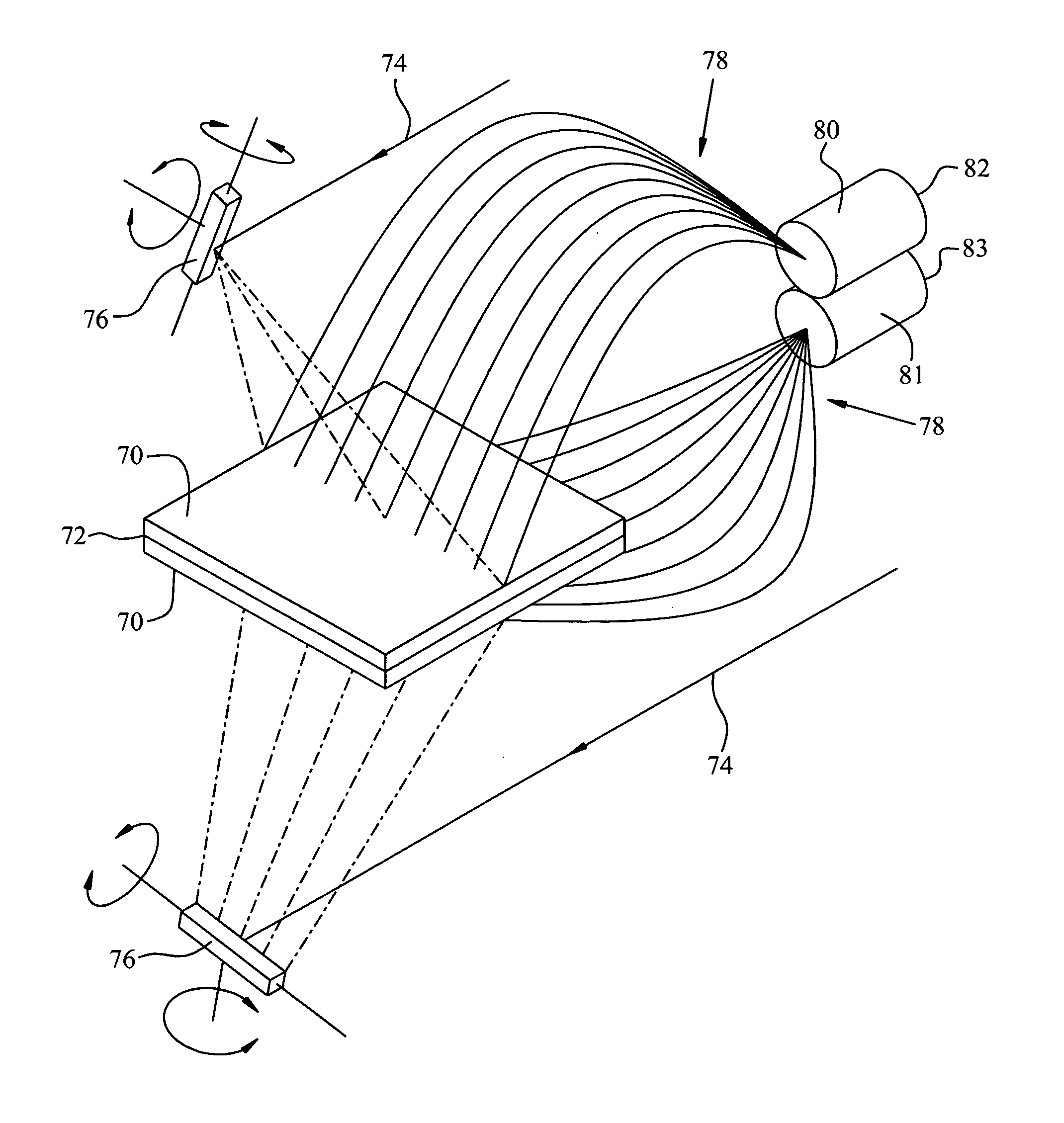
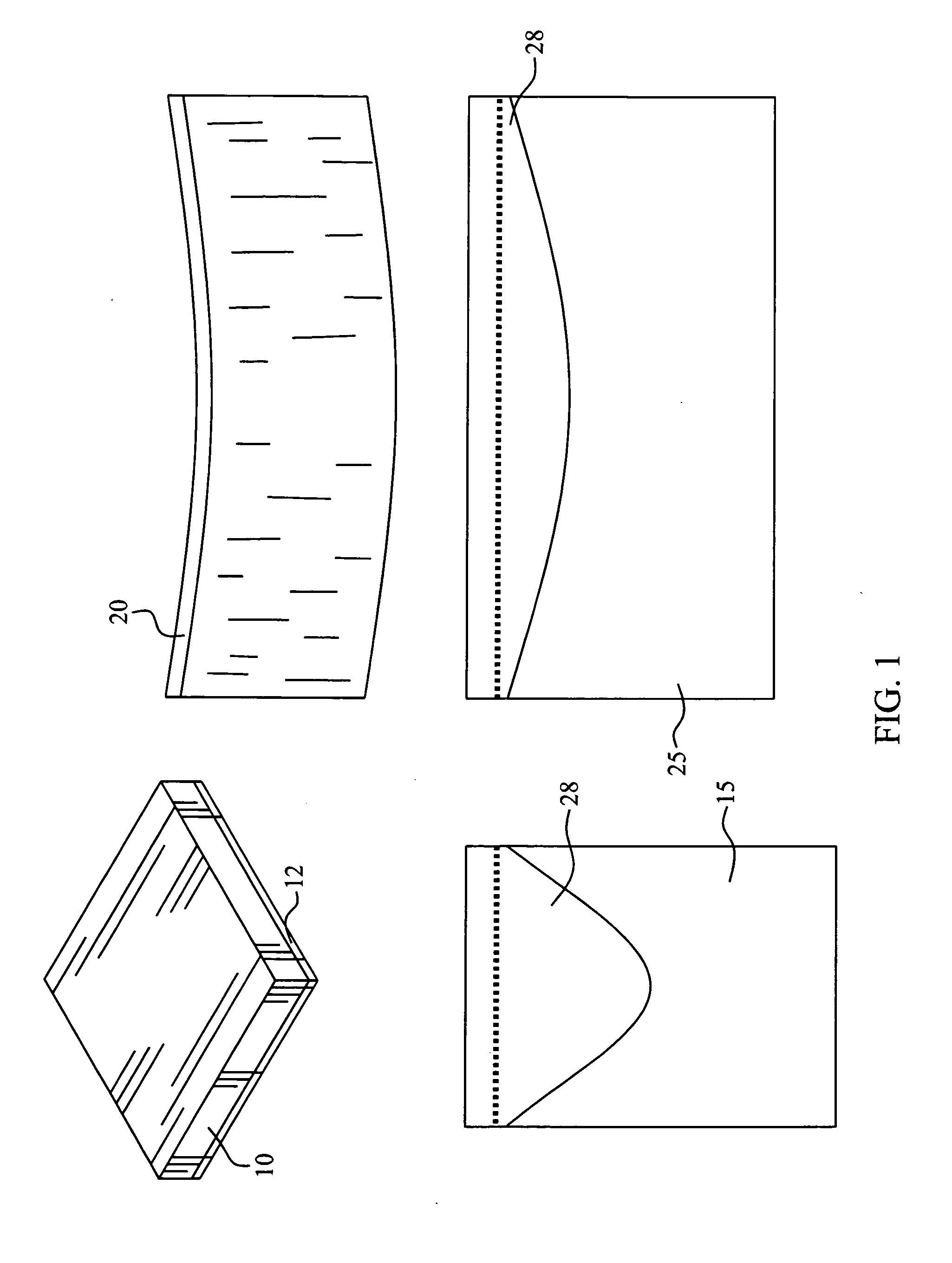
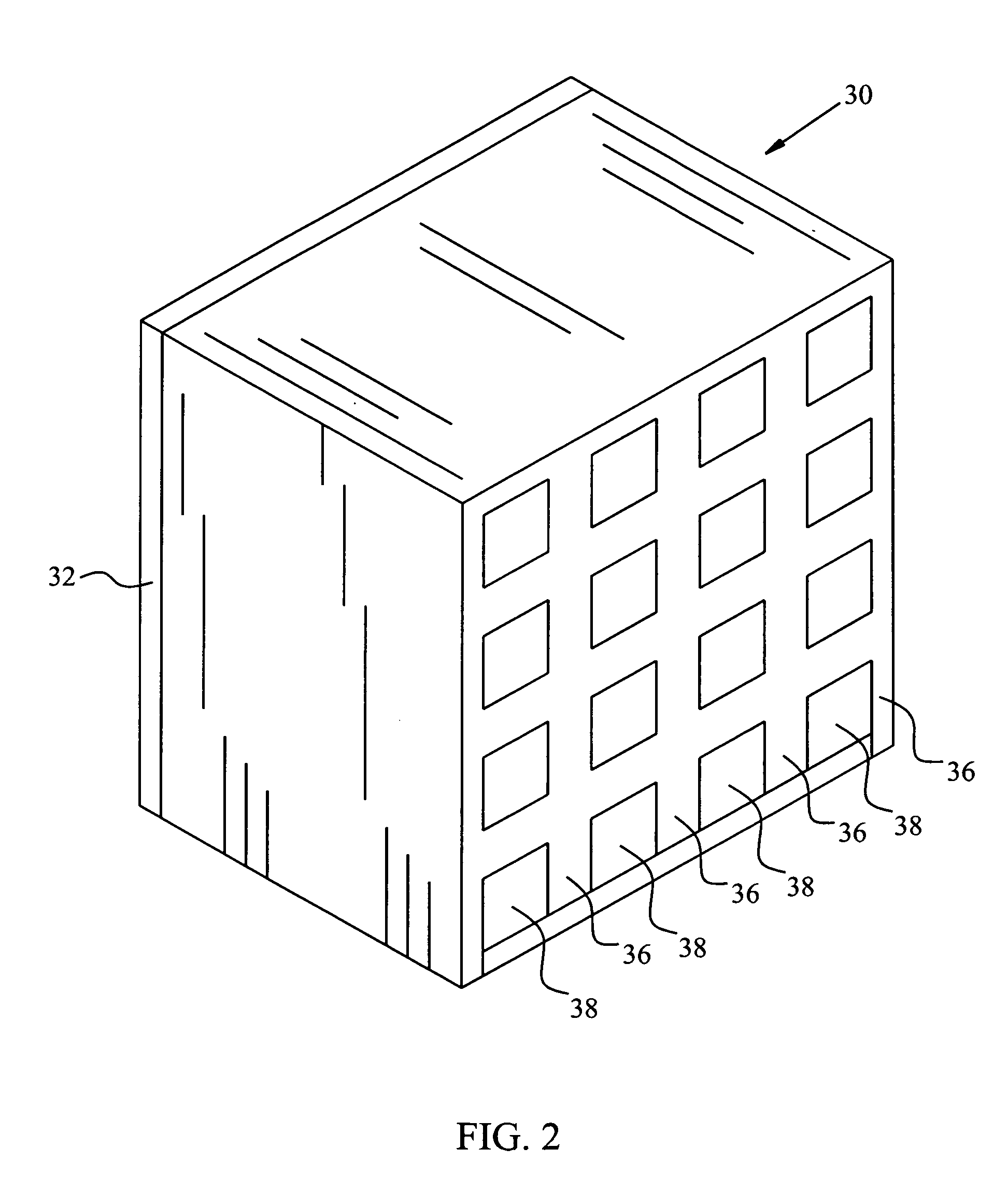
[0008]One implementation of the invention provides flat or shaped small area storage phosphor plates of one or more sizes suitable for intraoral imaging of one or more teeth by exposure to x-rays. Unexposed small area storage phosphor plates (bare or framed) are each sealed in protective storage phosphor carriers (SP-carriers) comparable to the carriers used with x-ray film (light-tight, impenetrable-by-liquids, x-ray transmissive). The SP-carrier, relative to the x-ray film carrier, offers comparable or easier positioning for the dentist and comparable or improved comfort levels for patients due to a reduction in size made possible by using the small area storage phosphor plate in place of film. The SP-carrier can incorporate a flap or frame that aids in maintaining the position of the detector in the patient's mouth (a feature frequently included for intraoral dental x-ray film carriers). A small area storage phosphor plate can be removed from its SP-carrier by manual or automated mechanical means prior to readout of the small area storage phosphor plate by a suitable optical scanning beam mechanism. An optional thin foil (or deposited layer) of an attenuating material (including alloys) such as copper, silver, lead, gold, etc. can be encapsulated and attached to, or incorporated into, the protective SP-carrier. This optional thin foil is located behind the small area storage phosphor plates (the front side of the storage phosphor plate is adjacent to the teeth) in order to provide additional radiation shielding for tissue. An alternative option is to attach the thin foils to the small area storage phosphor plate or its frame (if present). Multiple small area storage phosphor plates of the same or different storage phosphor materials can be stacked (comprising a hybrid storage phosphor plate), held within a SP-carrier, and used in place of a single small area storage phosphor plate within a SP-carrier for dental x-ray imaging. Hybrid storage phosphor plate can be used to attain dose reduction, energy resolution and contrast enhancement. In addition diagnostic imaging applications that utilize multiple particle types (for example fast and slow neutrons, neutrons and photons, etc.) can also utilize hybrid storage phosphor plates.

Problems solved by technology

Analog film storage and retrieval / transportation expenses may become issues over time.
Failure rates due to defective x-ray film are very low if film expiration dates are observed.
Well-known limitations of this imaging format include the use of the x-ray scintillator screen which blurs the incident x-ray signal, the limited dynamic range of the film, and possible non-uniformities in the chemical film-development process.
Limitations of digital x-ray cameras include high cost per unit (limiting the number of units a typical dental office can own), the size and rigidity of the camera (patient discomfort), the ability to damage the camera physically or by radiation, a cable (communications, power) that sticks out of the patient's mouth (discomfort) and general hygiene issues.
A well-known limitation for current implementations of storage phosphor plates used in x-ray mammography is that they offer relatively poor spatial resolution compared to mammography x-ray film-screen units.

Method used


Image

  • High resolution imaging system for digital dentistry
  • High resolution imaging system for digital dentistry
  • High resolution imaging system for digital dentistry

Examples


Embodiment Construction

[0017]The invention provides a digital dental x-ray imaging system that combines the positive attributes of dental analog x-ray film-screen detectors and digital dental x-ray cameras by utilizing available, high resolution, storage phosphor plate technology in a small area format combined with amplified photodetectors that generate an electronic signals resulting in a digital readout. One cost advantage associated with the small area storage phosphor plate format is the expected increase in manufacturing yield of small area imaging plates compared to large area imaging plates required for applications such as x-ray mammography. The invention provides cost-effective detector systems for digital x-ray dentistry with imaging properties comparable or superior to existing analog x-ray film-screen or digital x-ray cameras detector systems. Variations of this invention will be described that can be used for non-dental radiation detection applications (such as radiation monitoring with film...


PUM


Abstract

The invention provides methods and apparatus for detecting radiation including x-ray photon (including gamma ray photon) and particle radiation for dental x-ray imaging, radiation monitoring, and related industrial and scientific applications. Flat or shaped small (and small hybrid) area storage phosphor plates, available in multiple sizes, are encased in SP-carriers and used as detectors for intraoral dental x-ray imaging as a replacement for analog x-ray film and digital x-ray cameras, offering good detection efficiency, high spatial and contrast resolution, and a wide dynamic range. After removal of the SP-carrier, a small area storage phosphor plate is loaded into a dental storage phosphor scanner for readout. Intermediate and large area storage phosphor plates (including hybrid versions) are suitable for non-intraoral dental x-ray imaging. Suitable storage phosphors may be used in radiation monitoring, replacing current detectors employed in a film badge format. Simple external readers or electronic SP-carriers can provide data readout and thus enable dosimetry.

Description

[0001]This is a continuation of provisional application No. 61 / 336,632 filed on Jan. 25, 2010.FIELD OF THE INVENTION[0002]This invention provides novel high resolution imaging systems and designs for use in digital dentistry that are also suitable for radiation monitoring and related industrial and scientific imaging applications.BACKGROUND OF THE INVENTION[0003]The dominant intraoral x-ray radiographic imaging system detector for dentistry uses analog x-ray film optically-coupled to an x-ray scintillator screen (a film-screen unit) which is encased in a flexible, sealed (light-tight, impenetrable-to-fluids) soft packet film holder or carrier. The carrier may be made of a material such as molded Styrofoam or a similar light weight material that is radiographically-transparent. Dental x-ray film-screen units and carriers can be designed to fit a range of patient mouth sizes. The size of the film typically exceeds the size of the x-ray scintillator screen for handling purposes. The x-...

Claims


Application Information

Patent Timeline
IPC IPC(8): A61B6/14
CPCA61B6/14A61B6/4216G21K4/00A61B6/4494G01T1/2012A61B6/4291G21K2004/06A61B6/51G01T1/2992G01T1/20
Inventor NELSON, ROBERT SIGURDNELSON, WILLIAM BERT
Owner MINNESOTA IMAGING & ENG
Learn More