Tire vulcanization forming mold

a technology of vulcanization and forming molds, which is applied in the field of vulcanization forming molds, can solve the problems of difficult cutting out, and achieve the effects of convenient manufacturing of segment molds, convenient replacement, and economical replacemen

Active Publication Date: 2011-07-28
FUJISEIKO +1
View PDF6 Cites 6 Cited by
  • Summary
  • Abstract
  • Description
  • Claims
  • Application Information

AI Technical Summary

Benefits of technology

[0015]In the invention according to Claim 1, the arc-shape mold blocks are detachably fitted and secured in the plurality of circumferential grooves which are formed on each segment mold with spaces in the tire width direction, the plurality of slit grooves are formed on each mold block to open on the side surface of the mold block, the tread pattern forming blades are detachably inserted into these slit grooves in the tire width direction, and the coming-off prevention engaging portions are provided on the slit grooves and the blades. Thus, it is possible to manufacture the segment molds easier than those in which blades are formed by being cut out as practiced in the prior art. In addition, where the blades are damaged, it is possible to change the blades only by detaching the same from the slit grooves of the mold blocks, and hence, the replacement is economical.
[0016]In the invention according to Claim 2, each segment mold is divided into the plurality of mold pieces in the tire width direction, the plurality of arc-shape mold blocks are arranged in respective spaces between the plurality of these mold pieces, the plurality of these mold pieces and the plurality of mold blocks are bodily secured by the bolt, the plurality of slit grooves are formed on each mold block to open on the side surface of the mold block, the tread pattern forming blades are detachably inserted into these slit grooves in the tire width direction, and the coming-off prevention engaging portions are provided on the slit grooves and the blades. Thus, as is the same as described in Claim 1, it is possible to manufacture the segment molds easily. Where the blades are damaged, it is possible to change the blades only, and thus, the replacement is economical. In addition, since the connections are made not to provide clearances between the side surfaces of the mold blocks and the mold pieces, passages which are for discharging gas during the vulcanization forming of a tire can be formed at equal accuracies.
[0017]In the invention according to Claim 3, the blades comprise sipe forming blades. Thus, particularly, where the sipe forming blades being a thin shape are deformed or damaged, it is possible to easily change the sipe forming blades following the separation of the mold blocks.
[0018]In the invention according to Claim 4, since the blades comprise the tread groove forming blades and the sipe forming blades, nothing is required to do but to simply machine the inner circumferential surfaces on the internal surfaces of the mold blocks, so that it is possible to manufacture the segment molds easily.
[0019]In the invention according to Claim 5, each segment mold has the protruding streaks which define grooves being continuous in the tire circumferential direction at the respective places between the plurality of mold blocks. Thus, by utilizing partition walls for the mold blocks, it is possible to form the grooves being continuous in the tire circumferential direction.
[0020]In the invention according to Claim 6, the slit grooves take the L-shape as viewed from the sides of the mold blocks, the blades comprise the L-shape metal plates which are respectively fitted in the L-shape slit grooves, and these L-shapes constitute the coming-off prevention engaging portions. Thus, it is possible to easily form the L-shape slit grooves on the mold blocks by wire cut electric discharge machining or the like, while it is possible to easily form the blades by press forming.

Problems solved by technology

However, particularly, sipe forming blades for forming sipes take the form of a thin plate, and thus, difficulties arise in cutting them out.

Method used


Image

  • Tire vulcanization forming mold
  • Tire vulcanization forming mold
  • Tire vulcanization forming mold

Examples


Embodiment Construction

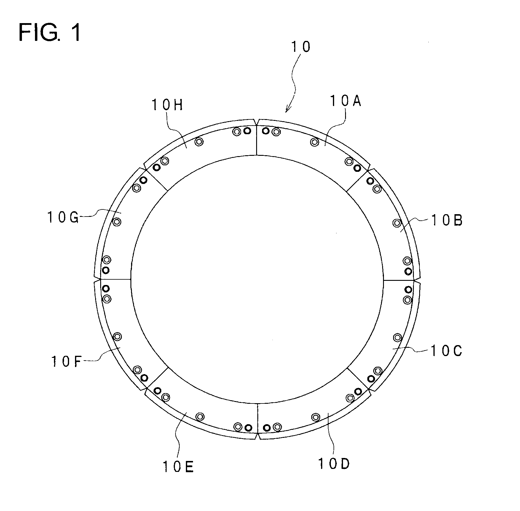
[0032]Hereafter, a first embodiment of the present invention will be described with reference to the drawings. FIG. 1 shows a mold 10 for vulcanizing and forming a tire, and the mold 10 is composed of segment molds 10A-10H which are divided into, for example, eight segments in the circumferential direction for forming a tread surface of the tire (not shown). The respective segment molds 10A-10H are the same in construction, and therefore, the construction of the segment mold 10A will hereafter be described in detail.

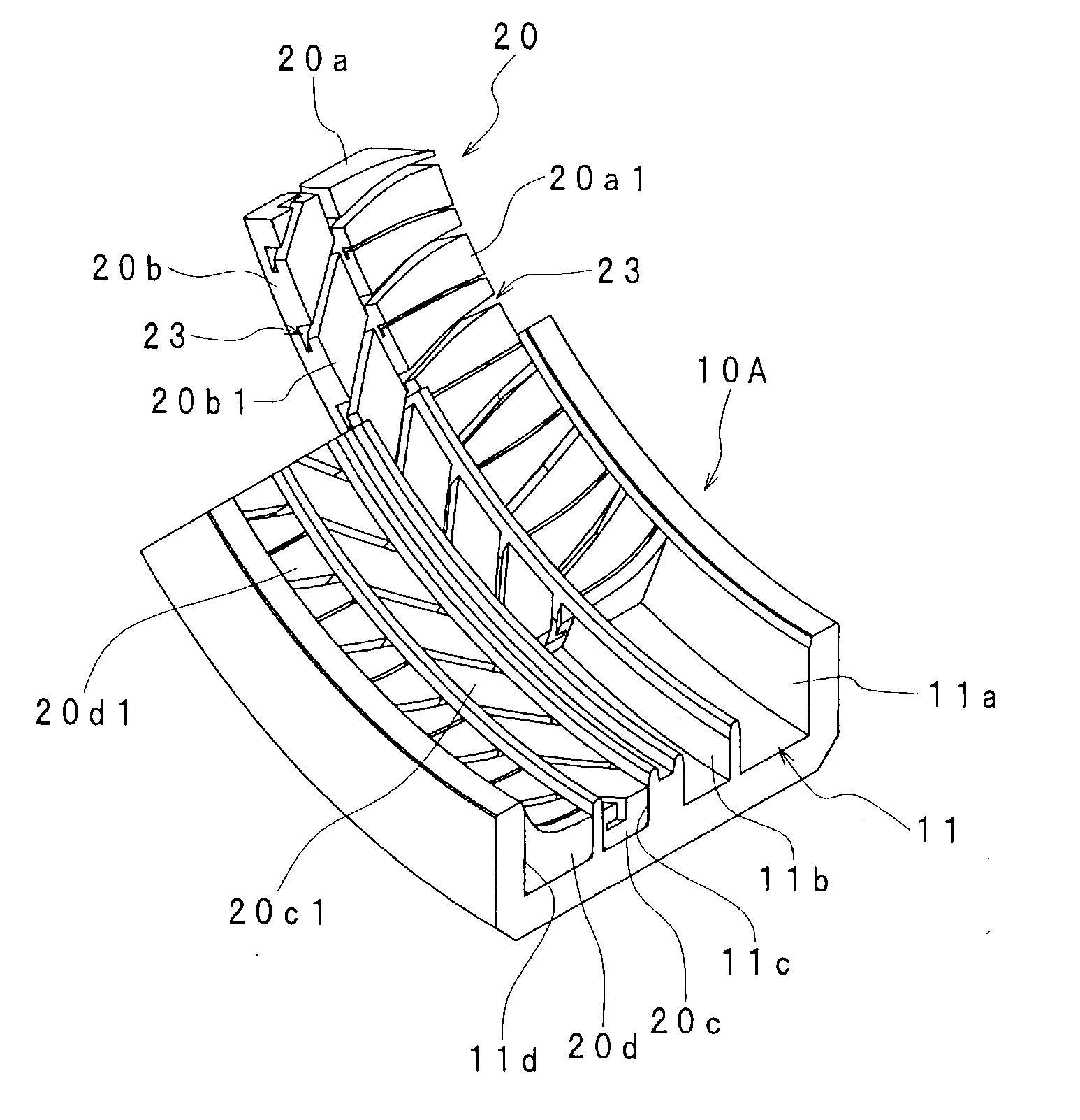
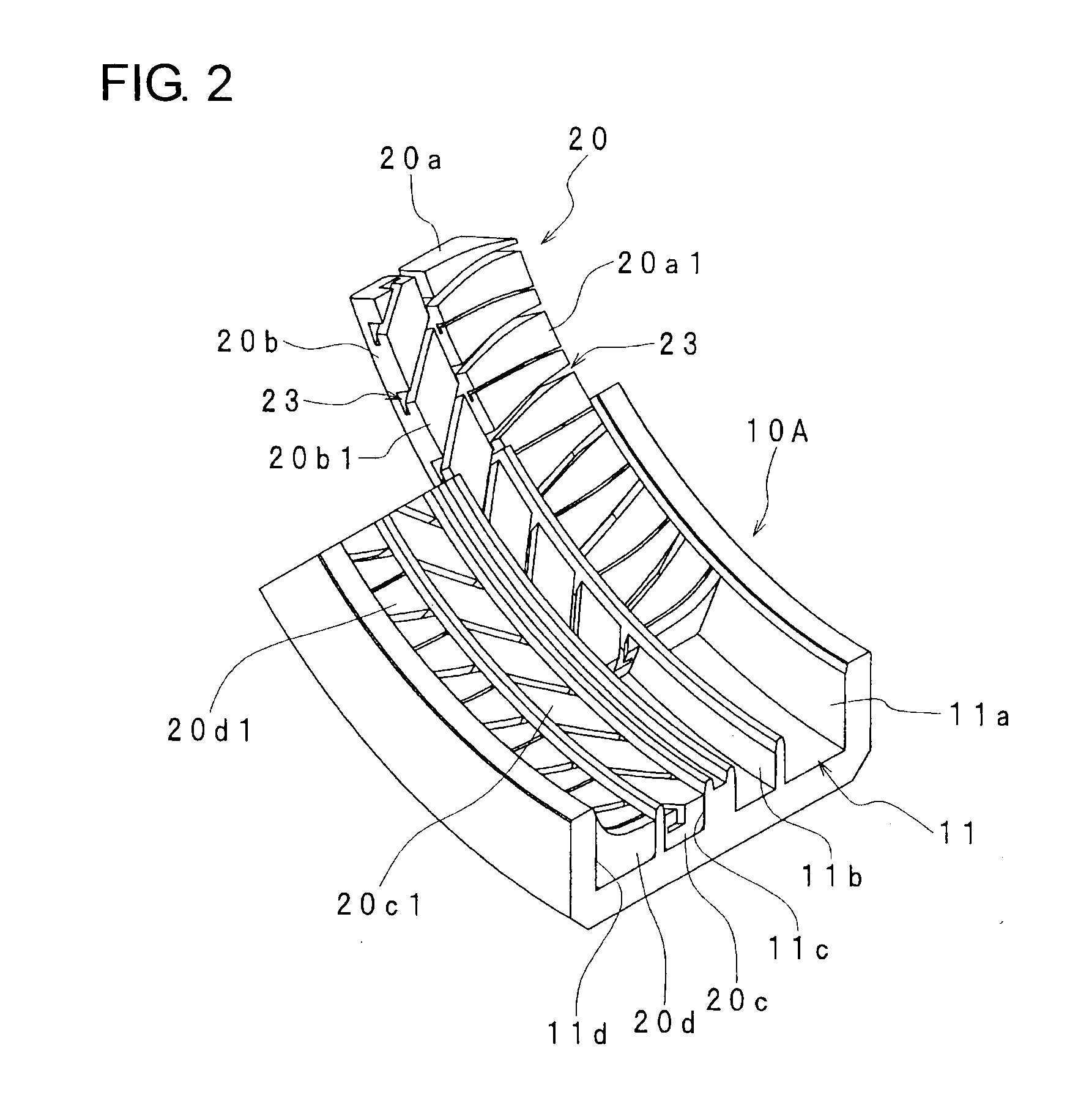
[0033]As shown in FIGS. 2, 3 and 4, on an internal surface of the segment mold 10A, a plurality of circumferential grooves 11 are formed with spaces in the width direction (tire width direction). In the embodiment, one example is illustrated as a case that four circumferential grooves 11a, 11b, 11c, 11d are formed with spaces therebetween in the width direction. The segment mold 10A has partition walls 13a, 13b, 13c formed at respective places between the circumferential...


PUM

PropertyMeasurementUnit
stressaaaaaaaaaa
stressaaaaaaaaaa
widthaaaaaaaaaa

Abstract

In a tire vulcanization forming mold which is circumferentially divided into a plurality of segment molds, a plurality of circumferential grooves are formed on each segment mold with spaces in a tire width direction; arc-shape mold blocks are detachably fitted respectively in the plurality of circumferential grooves; a plurality of slit grooves are formed on each mold block to open on side surfaces of the mold block; tread pattern forming blades are detachably inserted into these slit grooves in the tire width direction; and coming-off prevention engaging portions are provided on the slit grooves and the blades. Thus, the tire vulcanization forming mold is capable of enabling the blades to be replaced easily with respect to the segment molds.

Description

TECHNICAL FIELD[0001]The present invention relates to a tire vulcanization forming mold comprising segment molds which are divided in the circumferential direction for forming a tread pattern on a tire, and particularly, it relates to a tire vulcanization forming mold in which blades for forming a tread pattern are enabled to be attached or detached with respect to segment molds.BACKGROUND ART[0002]In forming a tire, there is used a mold which applies a pressure to the inside of a formed green tire and brings the outer surface of the green tire into pressure contact with the inner wall of the heated mold to vulcanize the green tire with heat and under pressure. On the internal surface side (on a tread side of the tire) of such a mold, a plurality of blades are provided for forming a tread pattern on the tire. The blades comprises circumferential groove forming blades (protruding streaks) for forming grooves being continuous in the circumferential direction of the tire, tread forming...

Claims


Application Information

Patent Timeline
Patent Type & Authority Applications(United States)
IPC IPC(8): B29D30/06B29C33/00
CPCB29D2030/0613B29D30/0606B29C33/02B29C35/02B29L2030/00
Inventor TAKAGI, CHIKARATANAKA, TATSUMI
Owner FUJISEIKO
Why Eureka
Try Eureka