Clamp for clamping a blade for a wind turbine and method of installing wind turbine blades

a technology for wind turbines and clamps, which is applied in the direction of machines/engines, manufacturing tools, and final product manufacture, etc., can solve the problems of not allowing rotation of hubs, direct drive turbines or turbines without gearboxes or turning gears, and difficult installation of wind turbines, so as to reduce the cost of clamping and simplify the construction of clamps. , the effect of improving the installation method and simplifying the construction

Inactive Publication Date: 2011-08-04
SIEMENS AG
View PDF10 Cites 42 Cited by
  • Summary
  • Abstract
  • Description
  • Claims
  • Application Information

AI Technical Summary

Benefits of technology

[0051]Thereby, in particular, the clamping of the blade between the first contact surface and the second contact surface as well as the adjustment of the orientation of the bar relative to the first contact area may be achieved by hydraulic cylinders thus requiring only one type of actuator to simplify the construction of the clamp and reduce the costs of the clamp in particular during operation. In particular, conventional hydraulic oil systems may be used to actuate the hydraulic cylinders comprised in the clamp.
[0052]According to an embodiment, the clamp further comprises a drawing and fixing apparatus and a wire, wherein the drawing and fixing mechanism is configured for drawing the wire and fixing the wire. In particular, the drawing and fixing apparatus may be adapted to guide a wire at least approximately along or parallel to a longitudinal direction of the first contact surface such that the wire may be drawn or may be released controlled by a control system. Further, the drawing and fixing apparatus may comprise at least one roller for rolling the wire in and / or out, wherein the roller may be driven by an actuator, such as an electromotor. The wire may be led over one or more rollers comprised in the drawing and fixing apparatus and may also be led over a roller connected to the crane lifting the clamped blade. By controlling the rolling in and / or rolling out of the wire the blade may be turned or steered according to requirements during installing the blade to the hub of the wind turbine. Thereby, the installation method using the clamp may still further be improved.

Problems solved by technology

Other wind turbines, called direct drive turbines or turbines without a gearbox or turning gear, do not allow rotating the hub by an actuator because a torque sufficient to rotate the hub cannot be generated.
Those wind turbines only allow rotating the hub during normal operation when converting the wind energy into mechanical energy by driving the blades by the impinging air.
However, for this method a turning gear is required or a crane, to rotate the rotor hub.
It turned out that the installation of a wind turbine is a difficult task due to the large size of the blades and due to the large weight of the blades.

Method used


Image

  • Clamp for clamping a blade for a wind turbine and method of installing wind turbine blades
  • Clamp for clamping a blade for a wind turbine and method of installing wind turbine blades
  • Clamp for clamping a blade for a wind turbine and method of installing wind turbine blades

Examples


Embodiment Construction

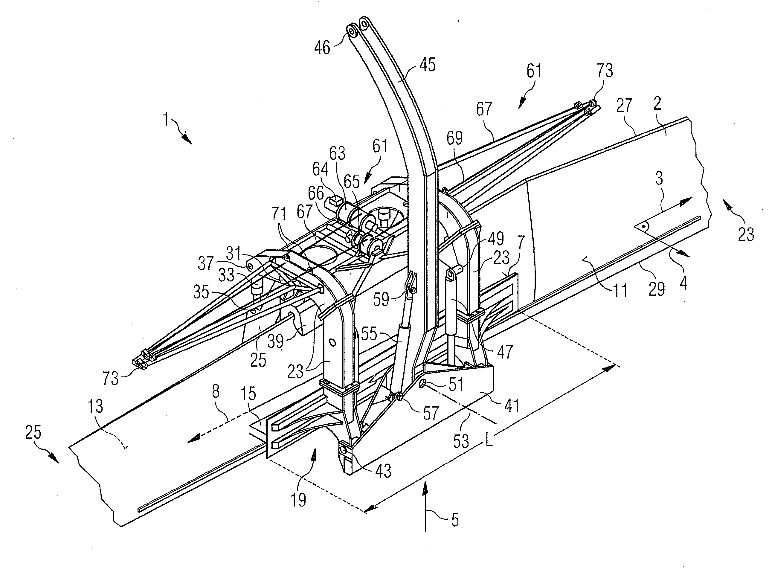
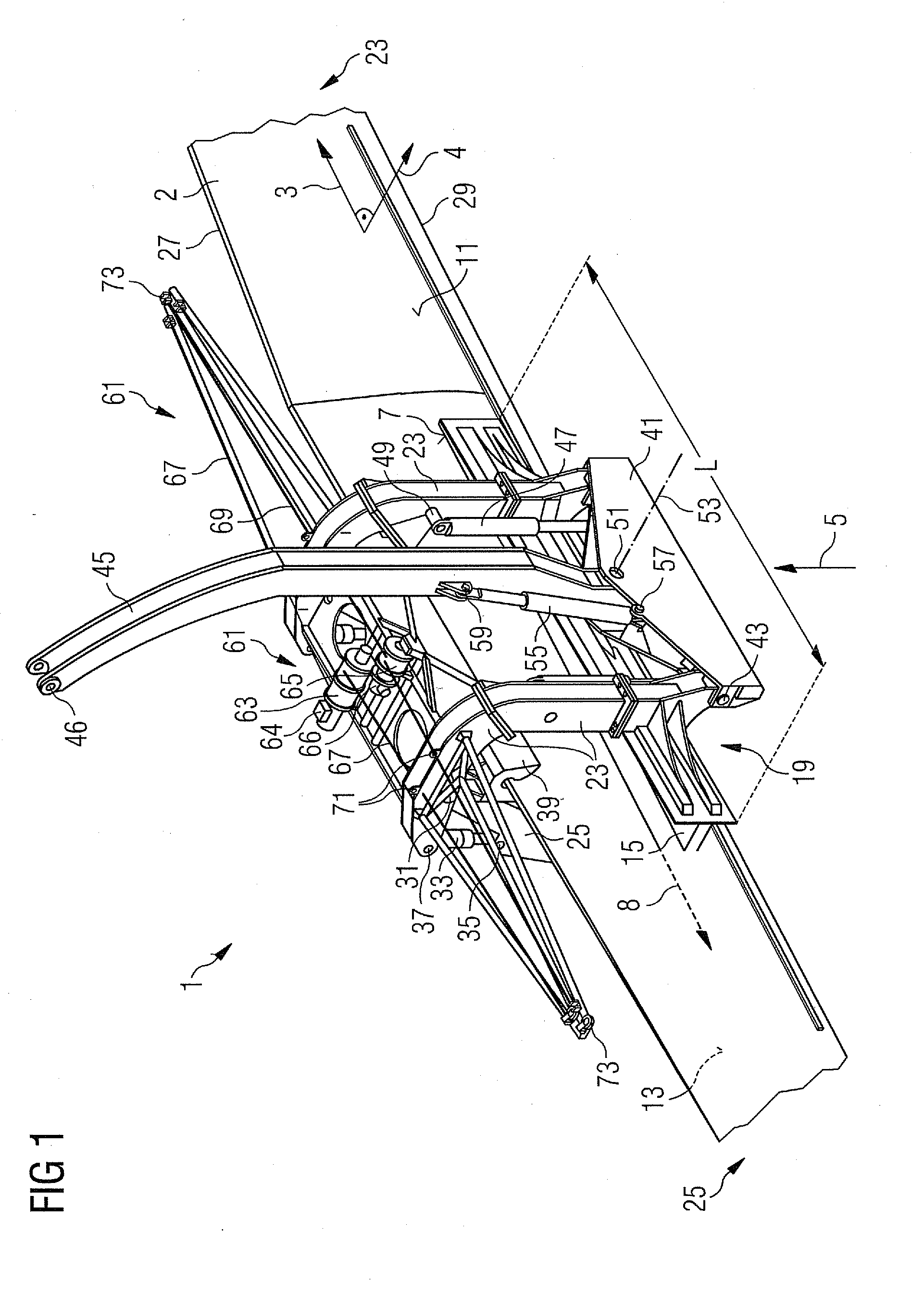
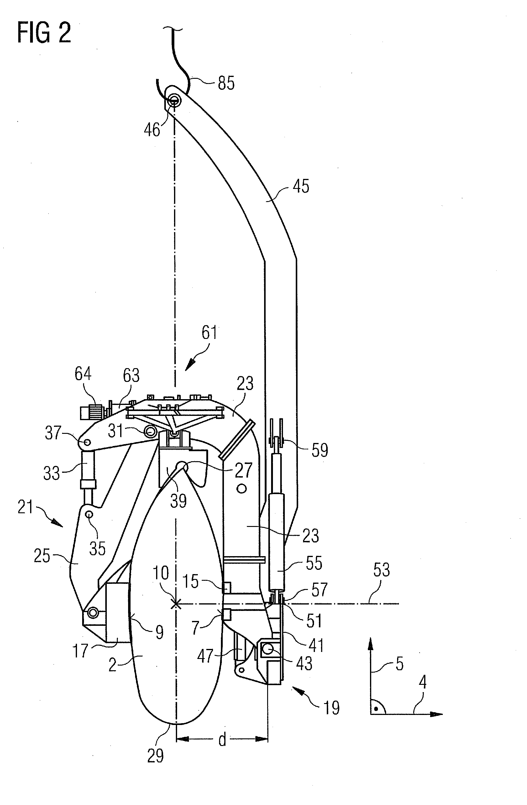
[0061]FIG. 1 shows a perspective view of a blade 1 according to an embodiment. The clamp 1 is illustrated in FIG. 1 while clamping a blade 2 for a wind turbine. A side view of the clamp 1 in a direction 3 indicated in FIG. 1 is illustrated in FIG. 2. A bottom view along the direction 5 illustrated in FIG. 1 is illustrated in FIG. 3.

[0062]The clamp 1 comprises a first contact surface 7 and a second contact surface 9. The first contact surface 7 and the second contact surface 9 are adapted to contact different portions of a surface of the blade 2. In the illustrated embodiment the first contact surface 7 contacts a portion of a back surface 11 of the blade 2, while the contact surface 9 of the clamp 1 contacts a portion of a front face 13 of the blade 2. While FIGS. 1 and 2 illustrate a state of the clamp 1, wherein the first contact surface 7 contacts the portion of the back surface 11 and the second contact surface 9 of the clamp contacts a portion of the front surface 13 of the bla...


PUM

PropertyMeasurementUnit
rotation anglesaaaaaaaaaa
heightaaaaaaaaaa
diameteraaaaaaaaaa

Abstract

A clamp for clamping a blade for a wind turbine is provided. The clamp includes a first contact surface adapted to contact a portion of a surface of the blade and a second contact surface adapted to contact another portion of the surface of the blade. The second contact surface is displaceable relative to the first contact surface. The clamp also includes a bar connected in an adjustable orientation relative to the first contact surface. Further, a method of installing wind turbine blades at a hub rotatable around a rotation axis along a horizontal direction is provided.

Description

CROSS REFERENCE TO RELATED APPLICATIONS[0001]This application claims priority of European Patent Office Application No. 10000317.7 EP filed Jan. 14, 2010, which is incorporated by reference herein in its entirety.FIELD OF INVENTION[0002]The present invention relates to a clamp for clamping a blade for a wind turbine and to a method of installing wind turbine blades at a hub. In particular, the present invention relates to a clamp for clamping a blade for a wind turbine and a method of installing wind turbine blades which are suitable for assembling a wind turbine which does not allow rotating its hub by an external actuator.BACKGROUND OF THE INVENTION[0003]A wind turbine is a machine which converts kinetic energy of moving air, such as wind, into mechanical energy. The mechanical energy may for example be converted into electrical energy by using a generator. Commonly in use are horizontal axis wind turbines which comprise a rotor shaft (rotatable around a horizontal axis) and a nac...

Claims


Application Information

Patent Timeline
Patent Type & Authority Applications(United States)
IPC IPC(8): B66C1/42B21D53/78B66C1/44
CPCB66C1/108B66C1/427B66C1/62F03D1/001Y10T29/49316F05B2260/30Y02E10/721Y02E10/728F05B2230/61F03D13/10Y02E10/72Y02P70/50
Inventor MAJ, KARL AAGEPOULSEN, HENNINGWILLIM, HANS-DIETER
Owner SIEMENS AG
Why Eureka
Try Eureka