Pressurized Fluid Positioner Control System

a positioner and control system technology, applied in fluid pressure control, thin material handling, instruments, etc., can solve the problems of high system cost, unnecessarily complex, and inability to afford all the benefits of inventive technology, so as to reduce component requirements, reduce maintenance, and reduce setup and operation costs

Inactive Publication Date: 2011-08-04
FLEXIBILITY ENG
View PDF54 Cites 1 Cited by
  • Summary
  • Abstract
  • Description
  • Claims
  • Application Information

AI Technical Summary

Benefits of technology

[0005]The benefits of exemplary embodiments disclosed herein may include system-wide efficiency, robustness of design leading to reduced component requirements, reduced maintenance, reduced setup and operation costs, and improved performance, as but two examples. More particular, advantages of certain embodiments of the inventive technology include but are not limited to: the provision of the ability to achieve an infinite number positioner responses (e.g., distances between side rails, for example) due to the infinite (perhaps “analog” type) number of pressures achievable by the system; the ability to reduce hysteresis observed in positioner response; the ability to simultaneously do the following: (a) alternatingly monitor (and adjust as necessary) a pilot pressure input 15 for each of a plurality of piloted regulators 8 while (b) automatically continually maintaining regulator output 14 pressure; and the use of only two connections between the valves 5 and piloted pressure regulator input 16 (which mitigates the risk of leaks, and may result in isolated pressure maintenance between valves and piloted pressure regulator for up to two days in some applications).
[0006]An additional advantage of particular embodiments is the provision of a continuous supply o

Problems solved by technology

There have been attempts in the past to provide position control systems that accurately adjust component(s), perhaps on a continual basis, to assure proper positioning by positioners and/or facilitate adjustments necessitate

Method used


Image

  • Pressurized Fluid Positioner Control System
  • Pressurized Fluid Positioner Control System
  • Pressurized Fluid Positioner Control System

Examples


Embodiment Construction

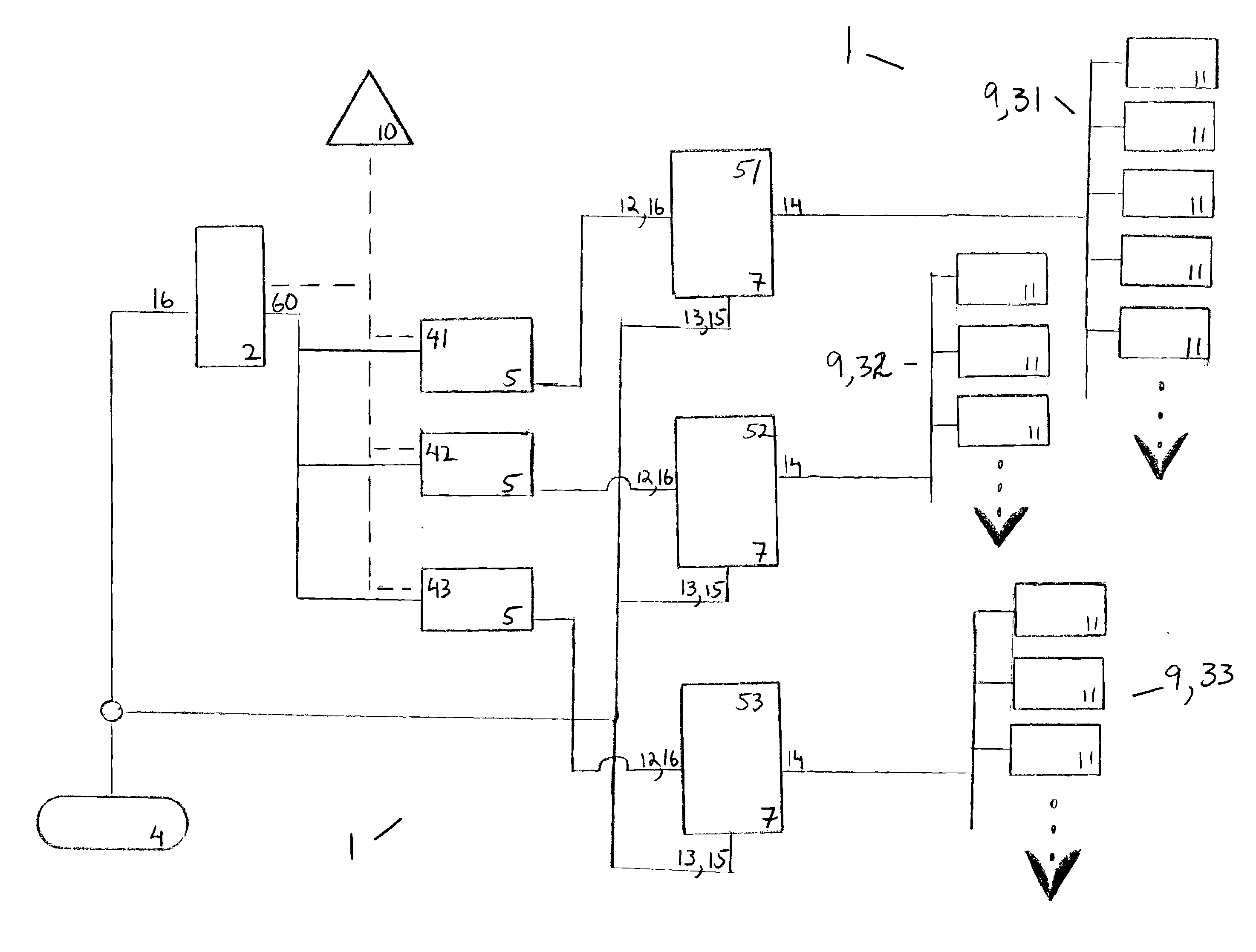
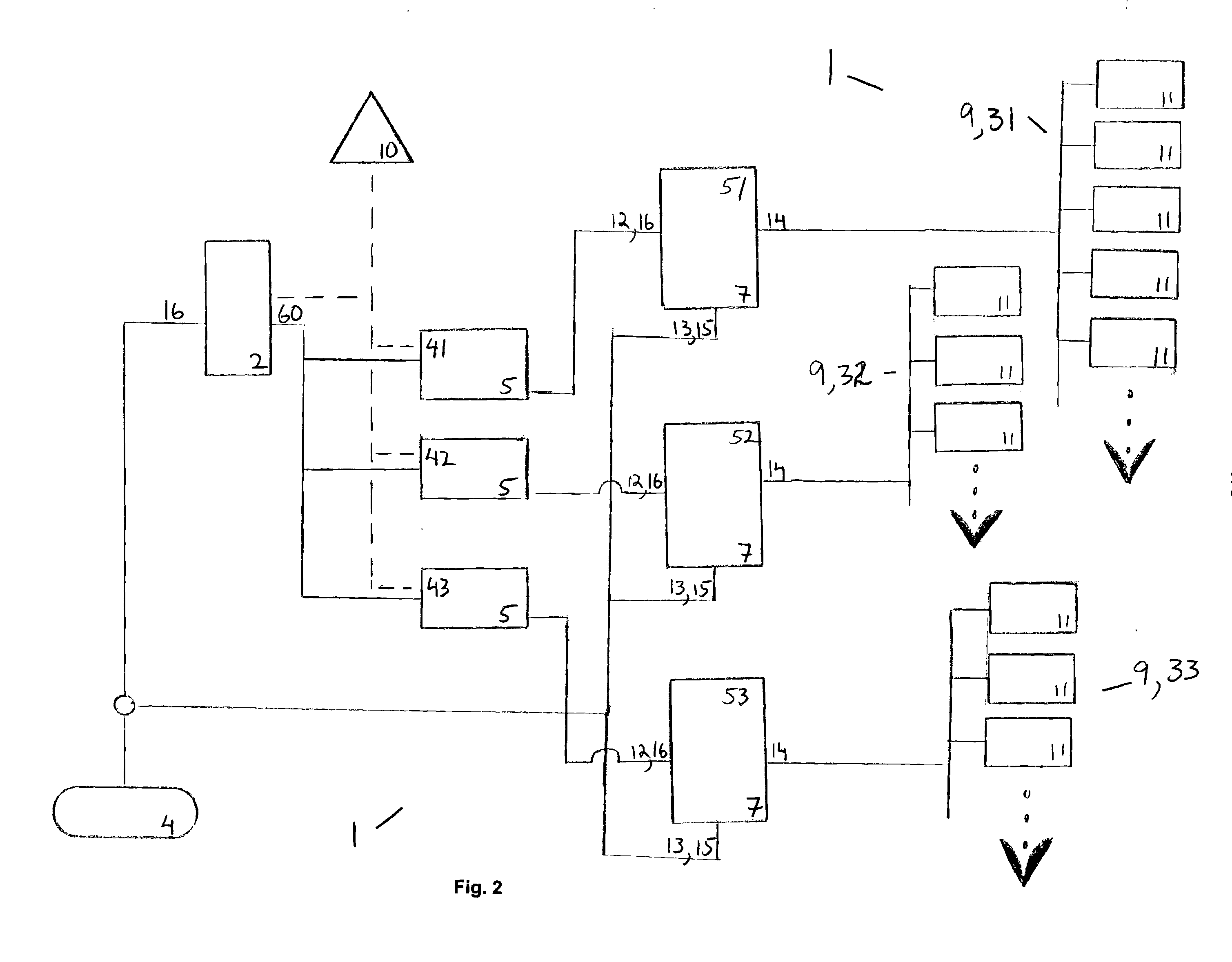
[0011]As mentioned earlier, the present invention includes a variety of aspects, which may be combined in different ways. The following descriptions are provided to list elements and describe some of the embodiments of the present invention. These elements are listed with initial embodiments, however it should be understood that they may be combined in any manner and in any number to create additional embodiments. The variously described examples and preferred embodiments should not be construed to limit the present invention to only the explicitly described systems, techniques, and applications. Further, this description should be understood to support and encompass descriptions and claims of all the various embodiments, systems, techniques, methods, devices, and applications with any number of the disclosed elements, with each element alone, and also with any and all various permutations and combinations of all elements in this or any subsequent application.

[0012]At least one embo...


PUM


Abstract

The inventive technology, in embodiments, may include a controller configured to coordinate operation of valves and remotely controllable regulators that are fluidically communicative therewith, allowing the control of positioners of positioner zones that are in fluidically communicative with such remotely controllable regulators. Preferred embodiments may find application as, e.g., a pneumatic system to control positioners, whether such positioner find use in bottling applications or elsewhere. Additional aspects of the inventive technology may relate to methods for pressurized fluid positioner control.

Description

BACKGROUND[0001]The need to accurately position—and reposition as a new application may require—one or more items for proper operation of systems and apparatus has been known in several industries for years. Perhaps the most well known such positioner is a side guide positioner, which may find application in the bottling industry to maintain proper position of containers (bottles or cans, as but two examples) as they travel along a conveyor during processing (filling, capping, etc.). A similar type of positioner may operate as part of a palletizing system to maintain the proper position of pallets as they travel along a conveyor, whether for pallet manufacture or pallet loading. Positioners may also find application as part of a differential valve controller, an HVAC mixing control system (as a substitute for expensive blowers), a solar panels (e.g., to maintain optimal orientation relative to the sun) and a programmable vehicle suspension system (where ground clearance is controlle...

Claims


Application Information

Patent Timeline
IPC IPC(8): G05D16/00
CPCG05D16/00Y10T137/2278Y10T137/87772Y10T137/87764Y10T137/7797F15B21/08
Inventor PAWELSKI, JOSEPH W.
Owner FLEXIBILITY ENG
Why Eureka
Try Eureka