Method and apparatus for autonomous downhole fluid selection with pathway dependent resistance system

a technology of resistance system and downhole fluid, which is applied in the direction of transportation and packaging, sealing/packing, borehole/well accessories, etc., can solve problems such as restricting fluid flow, and achieve the effect of restricting fluid flow

Active Publication Date: 2011-08-04
HALLIBURTON ENERGY SERVICES INC
View PDF102 Cites 162 Cited by
  • Summary
  • Abstract
  • Description
  • Claims
  • Application Information

AI Technical Summary

Problems solved by technology

Undesired fluids, such as natural gas or water in an oil well, are directed into the vortex chamber primarily tangentially, thereby restricting fluid flow.

Method used


Image

  • Method and apparatus for autonomous downhole fluid selection with pathway dependent resistance system
  • Method and apparatus for autonomous downhole fluid selection with pathway dependent resistance system
  • Method and apparatus for autonomous downhole fluid selection with pathway dependent resistance system

Examples


Embodiment Construction

[0034]While the making and using of various embodiments of the present invention are discussed in detail below, a practitioner of the art will appreciate that the present invention provides applicable inventive concepts which can be embodied in a variety of specific contexts. The specific embodiments discussed herein are illustrative of specific ways to make and use the invention and do not limit the scope of the present invention.

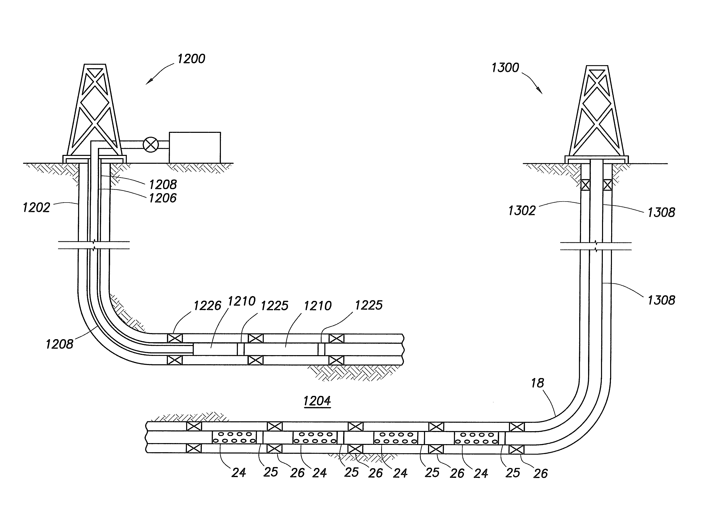
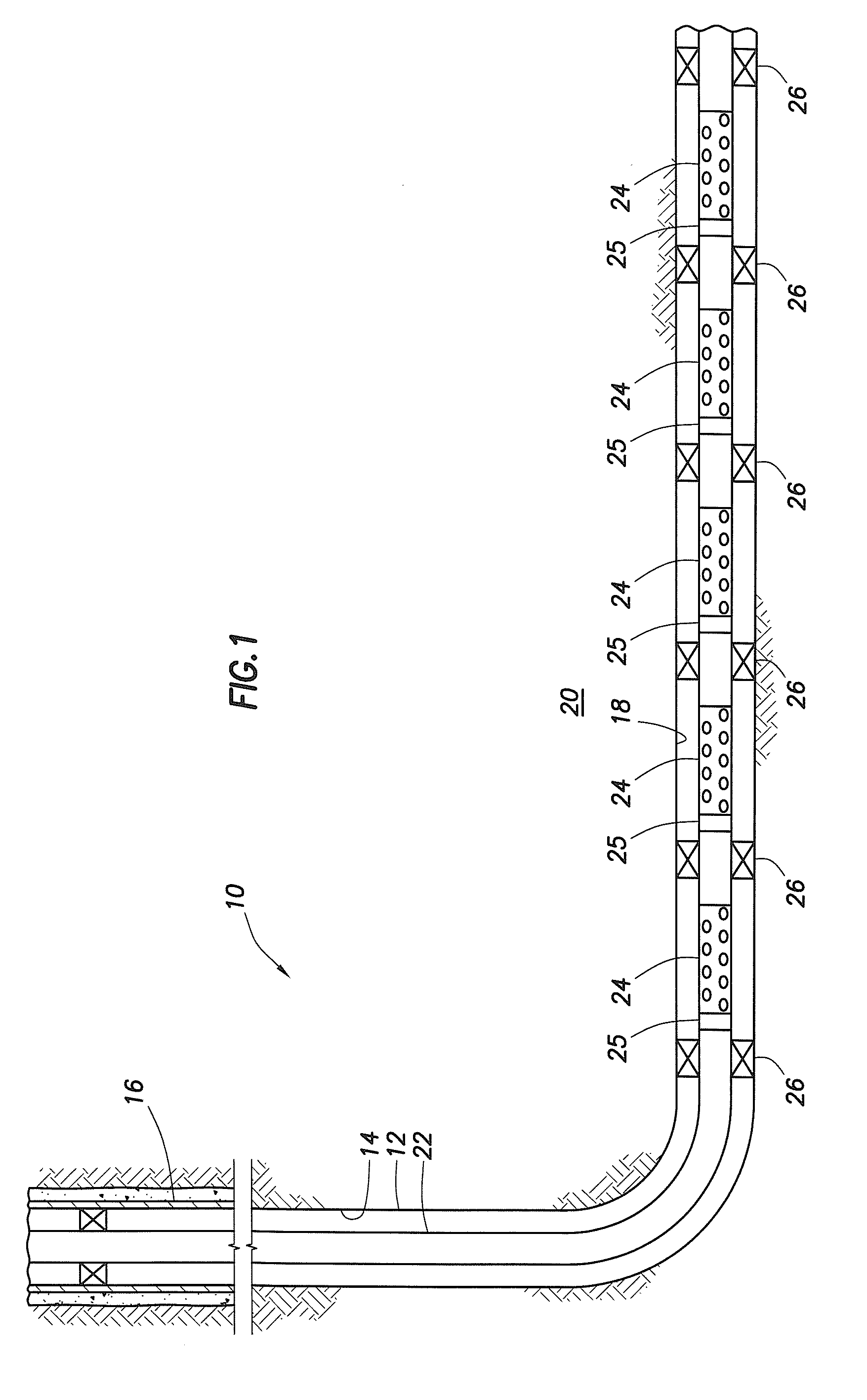
[0035]FIG. 1 is a schematic illustration of a well system, indicated generally 10, including a plurality of autonomous flow control systems embodying principles of the present invention. A wellbore 12 extends through various earth strata. Wellbore 12 has a substantially vertical section 14, the upper portion of which has installed therein a casing string 16. Wellbore 12 also has a substantially deviated section 18, shown as horizontal, which extends through a hydrocarbon-bearing subterranean formation 20. As illustrated, substantially horizontal section 18...


PUM


Abstract

An apparatus is described for controlling flow of fluid in a tubular positioned in a wellbore extending through a subterranean formation. A flow control system is placed in fluid communication with a main tubular. The flow control system has a flow ratio control system and a pathway dependent resistance system. The flow ratio control system has a first and second passageway, the production fluid flowing into the passageways with the ratio of fluid flow through the passageways related to the characteristic of the fluid flow. The pathway dependent resistance system includes a vortex chamber with a first and second inlet and an outlet, the first inlet of the pathway dependent resistance system in fluid communication with the first passageway of the fluid ratio control system and the second inlet in fluid communication with the second passageway of the fluid ratio control system. The first inlet is positioned to direct fluid into the vortex chamber such that it flows primarily tangentially into the vortex chamber, and the second inlet is positioned to direct fluid such that it flows primarily radially into the vortex chamber. Undesired fluids, such as natural gas or water, in an oil well, are directed, based on their relative characteristic, into the vortex primarily tangentially, thereby restricting fluid flow when the undesired fluid is present as a component of the production fluid.

Description

CROSS-REFERENCE TO RELATED APPLICATIONS[0001]NoneFIELD OF INVENTION[0002]The invention relates generally to methods and apparatus for selective control of fluid flow from a formation in a hydrocarbon bearing subterranean formation into a production string in a wellbore. More particularly, the invention relates to methods and apparatus for controlling the flow of fluid based on some characteristic of the fluid flow by utilizing a flow direction control system and a pathway dependant resistance system for providing variable resistance to fluid flow. The system can also preferably include a fluid amplifier.BACKGROUND OF INVENTION[0003]During the completion of a well that traverses a hydrocarbon bearing subterranean formation, production tubing and various equipment are installed in the well to enable safe and efficient production of the fluids. For example, to prevent the production of particulate material from an unconsolidated or loosely consolidated subterranean formation, certain c...

Claims


Application Information

Patent Timeline
Patent Type & Authority Applications(United States)
IPC IPC(8): E21B34/06E21B43/08F16L55/027
CPCE21B34/08E21B43/08F15C1/16E21B43/14E21B43/32E21B43/12E21B33/03Y10T137/2076Y10T137/2065Y10T137/2087Y10T137/212E21B34/06
Inventor DYKSTRA, JASON D.FRIPP, MICHAEL LINLEYDEJESUS, ORLANDO
Owner HALLIBURTON ENERGY SERVICES INC
Why Eureka
Try Eureka