System for controlling photomultiplier gain drift and associated method

Inactive Publication Date: 2011-08-04
COMMISSARIAT A LENERGIE ATOMIQQUE & AUX ENERGIES ALTERNATIVES
View PDF7 Cites 8 Cited by
  • Summary
  • Abstract
  • Description
  • Claims
  • Application Information

AI Technical Summary

Problems solved by technology

However, intrinsically, photomultipliers have drifts relating to their intrinsic operation (temperature and ageing problems).
A first disadvantage of such a system lies in the fact that the scintillating material ages significantly due to its being permanently exposed to the radiation and, as a consequence, the conversion efficiency between the energy deposited by the radiation and the quantity of light emitted by the scintillating material varies as the unit ages.
Consequently, the peak monitoring generally made no longer enables the photomultiplier's gain to be corrected nominally.
A second disadvantage is that, during low-level measurement, the fact of having a source present in the scintillator adds a background noise contribution which impairs

Method used


Image

  • System for controlling photomultiplier gain drift and associated method
  • System for controlling photomultiplier gain drift and associated method
  • System for controlling photomultiplier gain drift and associated method

Examples


first embodiment

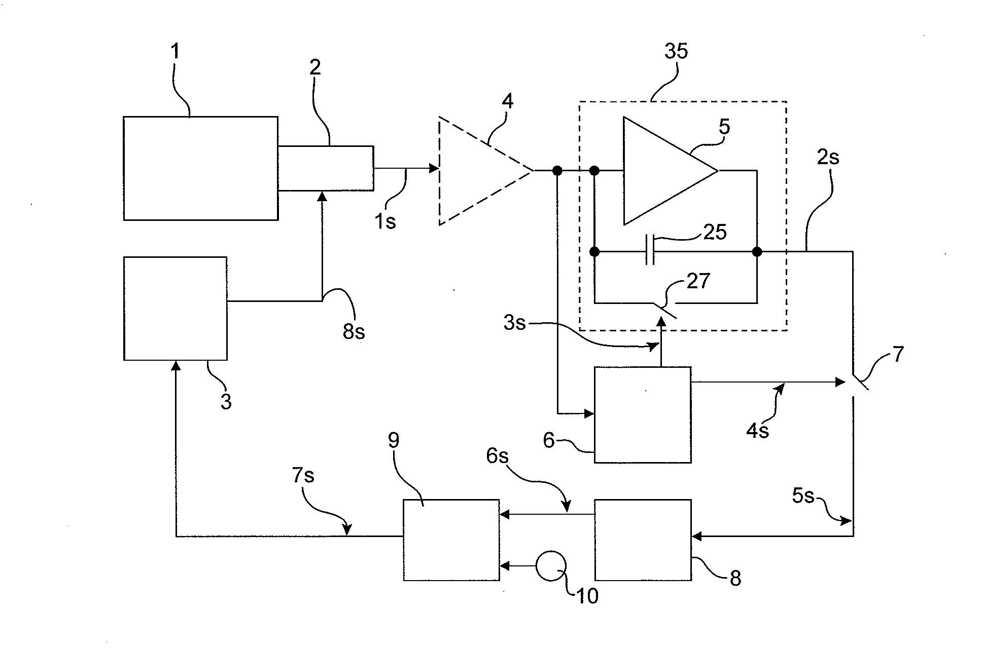
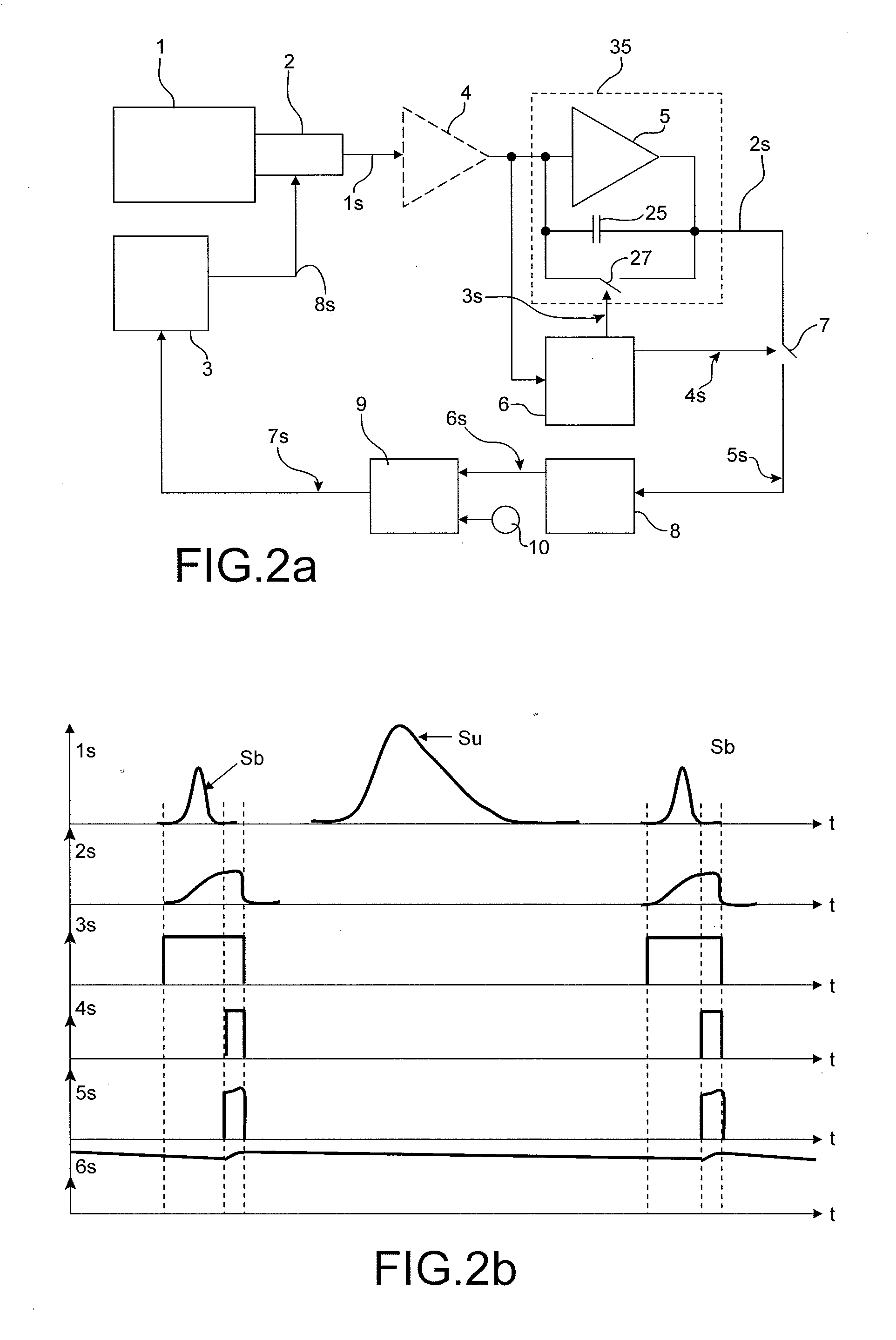
[0024]FIG. 2a represents a system for controlling photomultiplier gain drift according to the invention;

[0025]FIG. 2b represents various signals processed in a system in accordance with the system represented in FIG. 2a;

[0026]FIG. 3 represents a system for controlling photomultiplier gain drift according to a variant of the first embodiment of the invention;

[0027]FIG. 4 represents a system for controlling photomultiplier gain drift according to a second embodiment of the invention;

[0028]FIG. 5 represents a system for controlling photomultiplier gain drift according to a third embodiment of the invention;

[0029]FIG. 6 represents various signals processed in a system for controlling photomultiplier gain drift in accordance with the system represented in FIG. 5;

[0030]FIG. 7 represents an integrator used in variants of the invention;

[0031]FIGS. 8a and 8b represent filters which may be used in systems for controlling photomultiplier gain drift of the invention.

[0032]In all the figures th...


PUM


Abstract

A system for controlling photomultiplier gain drift is disclosed. According to one aspect, the system includes first means for measuring a noise signal of the photomultiplier, the first means configured emit a measurement signal representative of the photomultiplier's noise signal. The system further includes second means for maintaining the measured noise signal at a constant level, based on the measurement signal. The disclosed embodiments apply to stabilization of the gain of photomultipliers and, more specifically, to stabilization of neutron measurement systems using photomultipliers.

Description

TECHNICAL FIELD AND BACKGROUND[0001]The invention concerns a system for controlling photomultiplier gain drift and a method for controlling photomultiplier gain drift.[0002]The invention applies to the stabilisation of the gain of a photomultiplier used for spectrometry measurements or photon counting measurements in the fields of nuclear measurement and medical measurement.[0003]The invention also applies to the stabilisation of the neutron measurement systems using photomultipliers and also to the stabilisation of the gain of photomultipliers used in optical spectroscopy applications.[0004]A photomultiplier is a device allowing photons to be detected. It takes the form of an electronic tube. Under the action of light electrons are torn away from a bi-alkali-metal by a photoelectric effect from a photocathode, and the weak electrical current generated in this manner is amplified by a series of dynodes using the phenomenon of secondary transmission to obtain a substantial gain. Such...

Claims


Application Information

Patent Timeline
IPC IPC(8): H01J40/14G01T1/20
CPCH01J43/30H01J43/04
Inventor NORMAND, STEPHANEFRELIN, ANNE-MARIEHAMRITA, HASSENKONDRASOVS, VLADIMIR
Owner COMMISSARIAT A LENERGIE ATOMIQQUE & AUX ENERGIES ALTERNATIVES
Why Eureka
Try Eureka