Method and apparatus for cavitation threshold characterization and control

a technology of cavitation implosions and thresholds, applied in the direction of water supply installations, instruments, cleaning using liquids, etc., can solve the problems of cavitation cells not being able to be left in the process bath during operation, stable cavitation implosions emitting far less energy, etc., to achieve the effect of reducing chemical consumption

Active Publication Date: 2006-03-23
PROD SYST
View PDF15 Cites 39 Cited by
  • Summary
  • Abstract
  • Description
  • Claims
  • Application Information

AI Technical Summary

Benefits of technology

[0024] In commercial applications, the invention is used in acoustically enhanced chemical cleaning or other sonochemical processes, such as plating. In the cleaning case, this information is used to reduce chemical consumption by eliminating premature bath changes and prevent overdue bath changes from causing reduced PRE (particle removal efficiency) and the resulting loss of product due to particle compromised structures. The invention also allows adjustments to be made that avoid the damaging effects of transient cavitation.

Problems solved by technology

However, stable cavitation implosions emit far less energy, and are therefore undetectable by hydrophones, for practical purposes.
However, cavitation cells suffer from several problems.
For example, cavitation cells cannot be left in the process bath during operation because the probe needs to be in the energy field to make its measurements and the object being cleaned also needs to be in the field.
Additionally, the cell geometry does not guarantee that the fluid properties inside the cell are the same as what is in the tank, and gas buildup inside the cell affects data reproducibility.
A collapsing bubble in close proximity to the surface of a sensitive substrate can exert very high localized pressure and temperatures, causing structural damage to the substrate.
However, these processes lack real-time feedback to enable closed loop control of conditions in the cleaning tank based on cavitation level.

Method used


Image

  • Method and apparatus for cavitation threshold characterization and control
  • Method and apparatus for cavitation threshold characterization and control
  • Method and apparatus for cavitation threshold characterization and control

Examples


Embodiment Construction

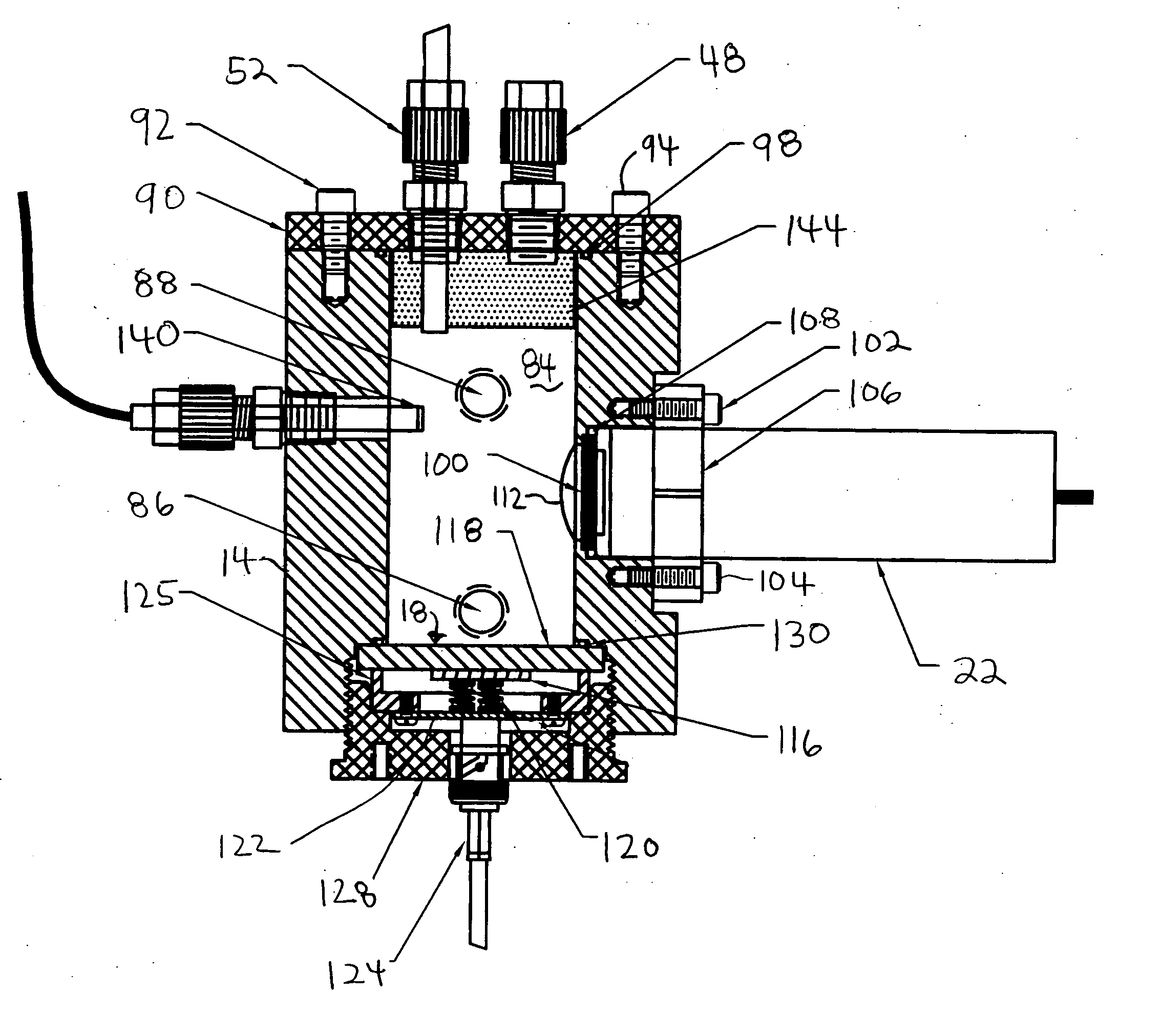
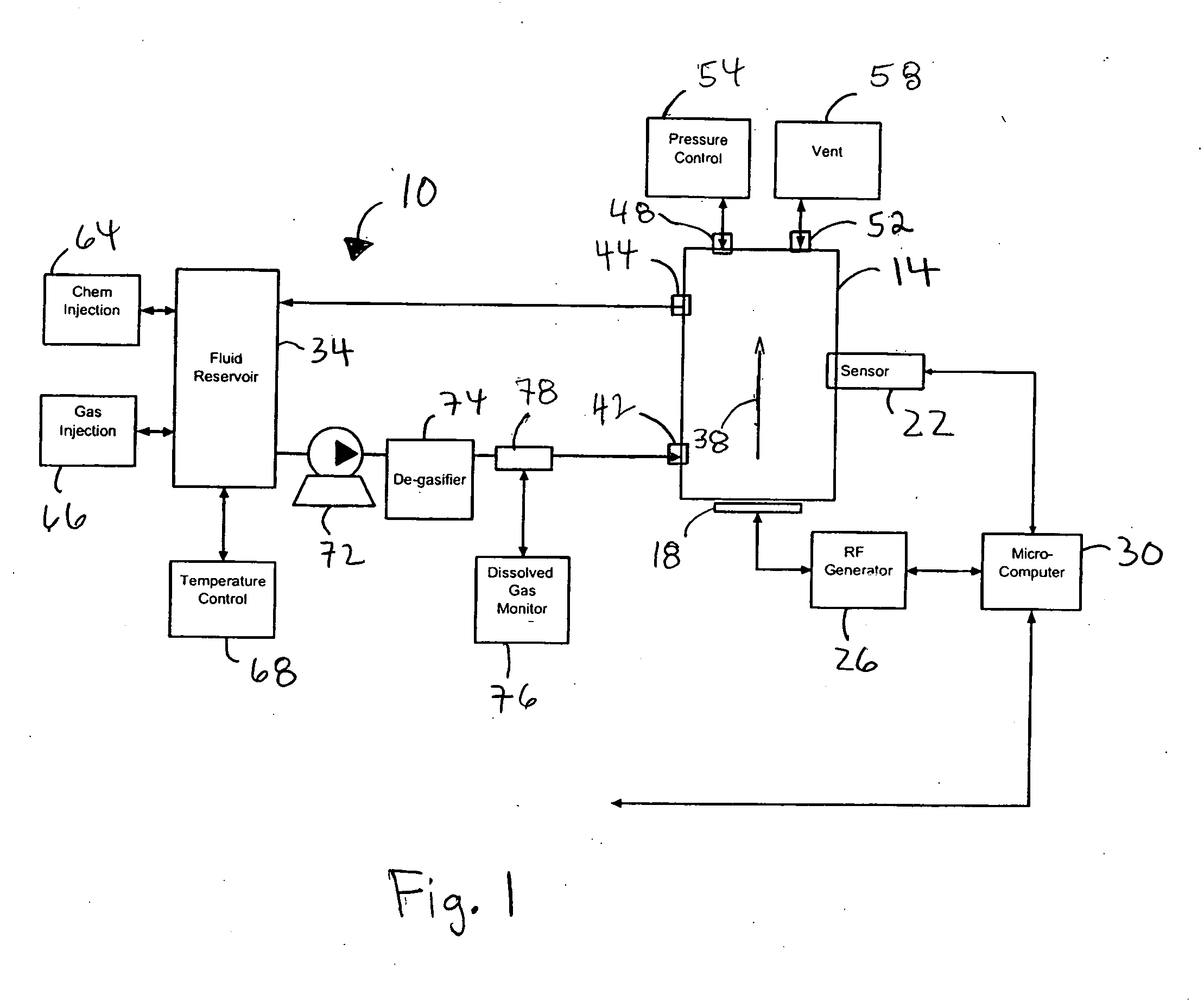
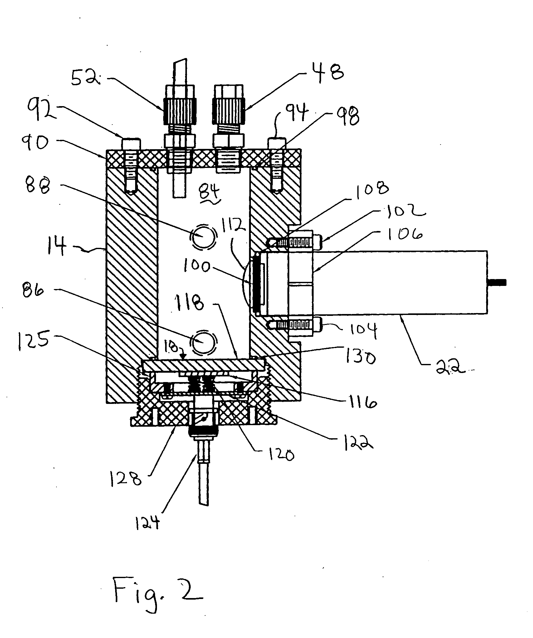
[0029]FIG. 1 illustrates a cavitation characterization system 10 comprised of a cavitation cell 14, an acoustic transducer 18 and a sensor 22. A power supply 26, such as a radio frequency (RF) generator, supplies power to the transducer 18. A microcomputer 30 controls the power supply 26 and collects data from the sensor 22. A fluid reservoir 34 provides a supply of a process fluid to the cell 14.

[0030] The cavitation cell 14 is a small light-tight chamber through which process fluids are caused to flow, usually in the direction of the arrow 38. Thus, the inside of the cell 14 contains a representative sample of the process fluid which is caused to cavitate by an acoustic field supplied by the transducer 18. The process fluid may be from a nearby tank, such as the fluid reservoir 34 in a research application, or it may be a sample of process fluid from a tank in production process equipment. The cell 14 must be sufficiently light-tight so as to allow detection of photon emission le...


PUM


Abstract

An apparatus and method for characterizing cavitation that occurs in a fluid exposed to acoustic energy. The apparatus comprises a vessel for holding the fluid; an acoustic energy generating means for generating acoustic energy, the acoustic energy generating means being positioned to transmit the acoustic energy into the fluid while the fluid is held in the vessel; and a cavitation detection means for detecting cavitation in the fluid held in the vessel. In a preferred embodiment, the cavitation detection means comprises a light detection means, such as a photomultiplier tube, that detects sonoluminescent emission from the fluid. The method comprises the steps of exposing a volume of process fluid to acoustic energy at a specified power level; measuring the photon output from the fluid over a period of time; and when the photon output deviates from a desired level, initiating a remedial step to bring the photon output back to approximately the desired level.

Description

CROSS-REFERENCE TO RELATED APPLICATIONS [0001] This application claims the benefit of priority of U.S. Provisional Patent Application 60 / 610,805, filed Sep. 17, 2004.BACKGROUND OF THE INVENTION [0002] 1. Technical Field [0003] The present invention relates to technology that uses acoustic energy transmitted through a fluid for cleaning or some other purpose, and more particularly to a system that uses the emission of light from the fluid when it is exposed to the acoustic energy (sonoluminesence) to avoid transient cavitation. [0004] 2. Background Information [0005] Historically, many industrial cleaning processes have made use of aqueous chemical fluids to remove particles from objects. In many cases, adding acoustic energy in the frequency range of 1 KHz to 10 MHz into the process bath has been shown to improve the cleaning process by removing particles more completely and in a shorter period of time. Introduction of acoustic energy into plating baths has also been shown to enhanc...

Claims


Application Information

Patent Timeline
Patent Type & Authority Applications(United States)
IPC IPC(8): H02K23/60
CPCB01J19/008B01J19/10B01J2219/00247B01J2219/0877B08B3/00G01N2291/02836G01H9/00G01N21/62G01N21/71G01N2021/1704B08B3/12Y10T137/0318H10N30/00
Inventor BECK, MARK J.LILLARD, RAYMOND Y.LIEBSCHER, ERIC G.HAIDINYAK, FRANK M.
Owner PROD SYST
Why Eureka
Try Eureka