Charged particle detection devices

a detection device and charge technology, applied in the direction of material analysis, instruments, heat measurement, etc., can solve the problems of mediocre collection efficiency and difficulty in achieving uniform signal collection

Active Publication Date: 2008-12-25
ASML NETHERLANDS BV
View PDF31 Cites 42 Cited by
  • Summary
  • Abstract
  • Description
  • Claims
  • Application Information

AI Technical Summary

Benefits of technology

[0011]This invention is directed to provide designs for an annular in-lens on-axis symmetrically distributed multi-channel detection system. The detectors can be Scintillator-PMT, semiconductor or micro-plate type and inclu...

Problems solved by technology

For the multiple detector arrangement the configuration is complicated and the signal collection efficiency is mediocre due to the spatial separation of the individual d...

Method used


Image

  • Charged particle detection devices
  • Charged particle detection devices
  • Charged particle detection devices

Examples


Embodiment Construction

[0027]Detection devices and more specifically to charged particles detection devices for are illustrated herein. The following description is presented to enable one of ordinary skill in the art to make and use the invention and is provided in the context of a patent application and its requirements. Various modifications to the preferred examples and the generic principles and features described herein will be readily apparent to those skilled in the art. Thus, the present invention is not intended to be limited to the examples illustrated, but is to be accorded the widest scope consistent with the principles and features described herein.

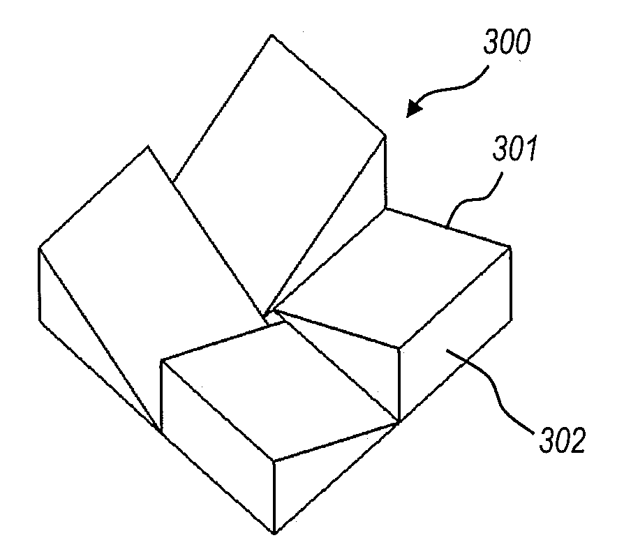
[0028]A first example of a charged particle detector assembly in accordance with the present invention will be described in detail with reference to FIG. 3A through FIG. 3J. FIG. 3A, FIG. 3B and FIG. 3C illustrate the tilted top view, tilted bottom view, and top view of the detector light guide assembly 300, respectively. As illustrated in FIG. 3A...


PUM


Abstract

A charged particle detector consists of a plurality independent light guide modules assembled together to form a segmented in-lens on-axis annular detector, with a center hole for allowing the primary charged particle beam to pass through. One side of the assembly facing the specimen is coated with or bonded to scintillator material as the charged particle detection surface. Each light guide module is coupled to a photomultiplier tube to allow light signals transmitted through each light guide module to be amplified and processed separately. A charged particle detector is made from a single block of light guide material processed to have a cone shaped circular cutout from one face, terminating on the opposite face to an opening to allow the primary charged particle beam to pass through. The opposite face is coated with or bonded to scintillator material as the charged particle detection surface. The outer region of the light guide block is shaped into four separate light guide output channels and each light guide output channel is coupled to a photomultiplier tube to allow light signal output from each channel to be amplified and processed separately.

Description

CROSS-REFERENCES TO RELATED APPLICATIONS[0001]This application is a Continuation of U.S. Ser. No. 11 / 668,846 filed Jan. 30, 2007, the disclosures of which are incorporated herein by reference.FIELD OF THE INVENTION[0002]The present invention relates generally to detection devices and more particularly to charged particles detection devices.BACKGROUND OF THE INVENTION[0003]A charged particle detector is the indispensable part of a charged particle (ion or electron beam) instrument, such as a scanning electron microscope (SEM). In a SEM, an electron beam emanated from an electron source is focused into a fine probe over a specimen surface and scanned by a deflection unit in a raster fashion; and signal electrons released from the specimen, including secondary electrons and back scattered electrons, are collected by charged particle detectors and the signal intensity is converted into the gray level of an image pixel corresponding to the location of the electron probe on the specimen s...

Claims


Application Information

Patent Timeline
IPC IPC(8): G01N23/00
CPCH01J37/244H01J37/28H01J2237/2443H01J2237/24435H01J2237/2445H01J2237/24465
Inventor WANG, JOEZHANG, XUCHEN, ZHONG-WEI
Owner ASML NETHERLANDS BV
Why Eureka
Try Eureka