Liquid ejection device

a liquid ejection device and printer technology, applied in printing, other printing apparatus, etc., can solve the problems of image blur, ink in the corresponding portion is not cured, and the intensity of ultraviolet light changes, and achieves high productivity

Inactive Publication Date: 2011-08-04
SEIKO EPSON CORP
View PDF2 Cites 0 Cited by
  • Summary
  • Abstract
  • Description
  • Claims
  • Application Information

AI Technical Summary

Benefits of technology

[0021]According to this configuration, even if there is an unsatisfactory ultraviolet light source in the ultraviolet radiation device, the radiation intensity can be supplemented by the

Problems solved by technology

However, in an ultraviolet radiation device comprising a plurality of ultraviolet light-emitting elements as in Japanese Laid-Open Patent Publication No. 2008-265285, when a problem occurs in one ultraviolet light-emitting element, the intens

Method used


Image

  • Liquid ejection device
  • Liquid ejection device
  • Liquid ejection device

Examples


first embodiment

[0031]An embodiment in which the present invention is specified as an inkjet printer (hereinbelow also sometimes shortened to “printer”), which is one type of a liquid ejection device, is described hereinbelow according to FIGS. 1 through 3.

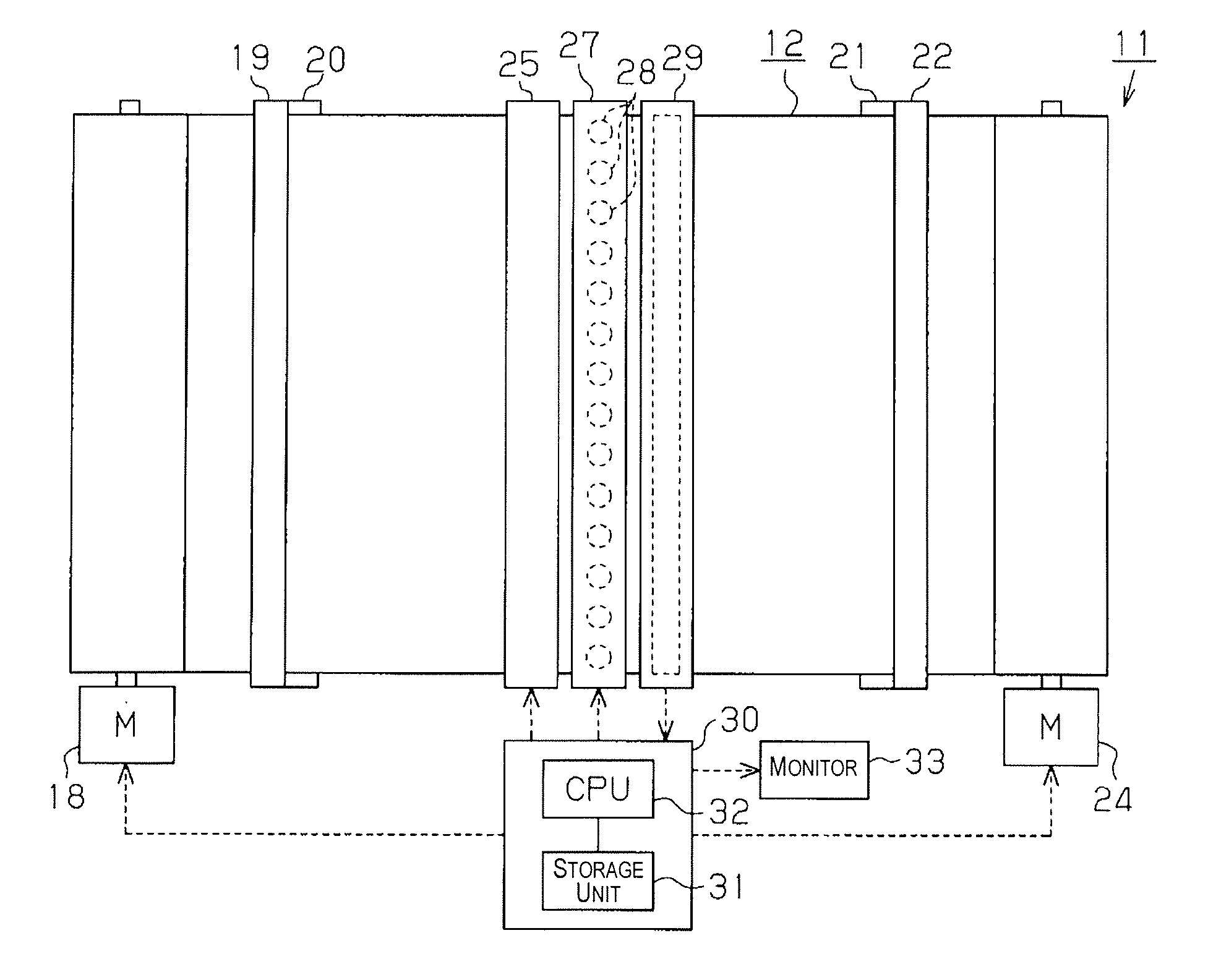
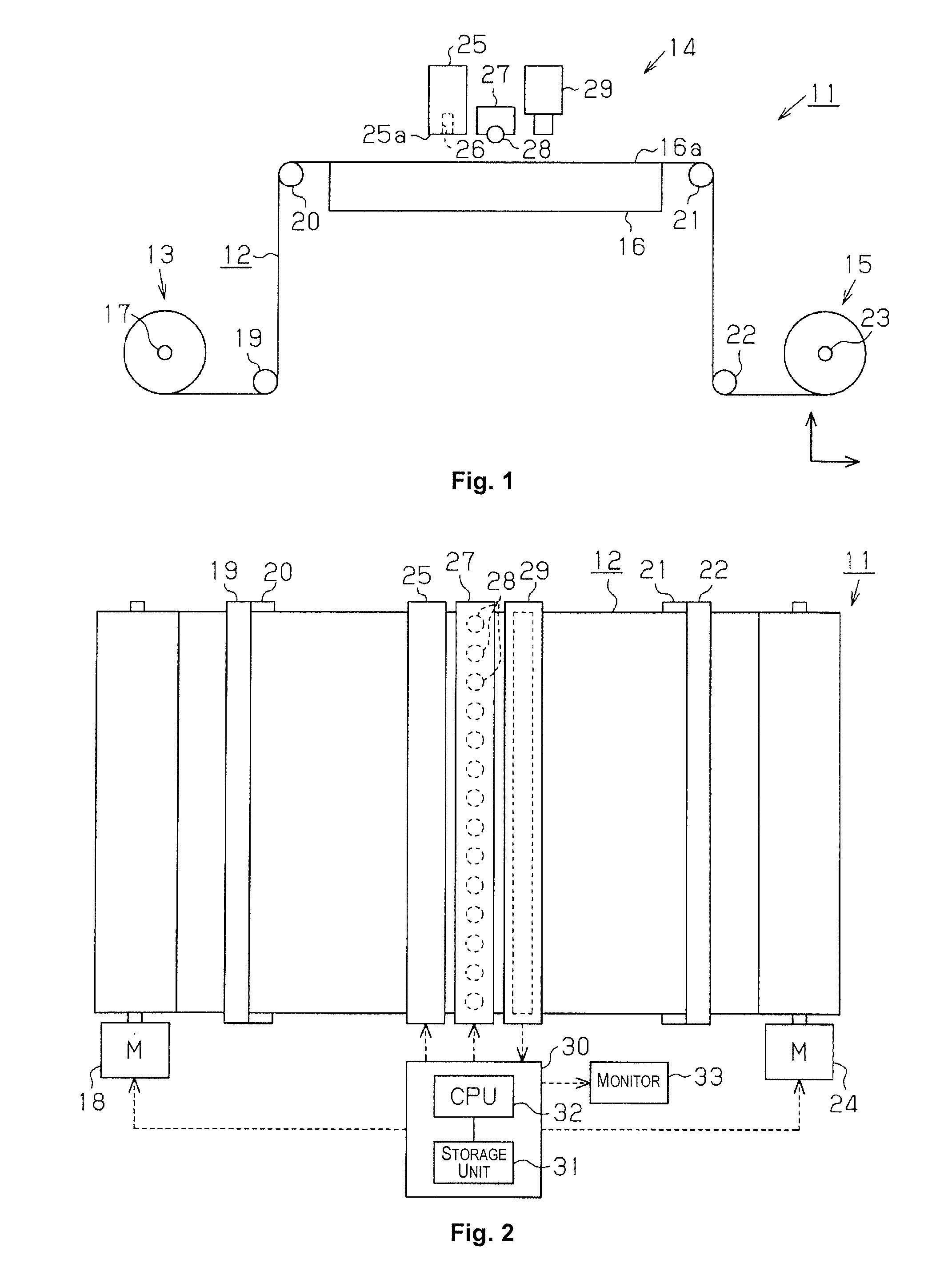
[0032]An inkjet printer 11 as a liquid ejection device is provided with an unreeling portion 13 for unreeling continuous paper 12 as a rectangular target, a printing portion 14 for performing a recording process by ejecting ink as a liquid onto the continuous paper 12, and a winding portion 15 for winding the continuous paper 12 on which the recording process has been performed, as shown in FIG. 1. The printing portion 14 is provided with a rectangular plate-shaped platen 16 capable of supporting the continuous paper 12.

[0033]That is, in the conveying direction of the continuous paper 12, the unreeling portion 13 is disposed in a position nearer to the left, which is the upstream side, and the winding portion 15 is disposed in a position nearer t...

second embodiment

[0057]Next, the second embodiment of the present invention is described based on FIGS. 4 and 5. To compare the second embodiment to the first embodiment, the configuration of the printing portion 14 is different in one respect, but the configuration is otherwise substantially identical to that of the first embodiment. Therefore, the description hereinbelow is primarily of the points that differ from the first embodiment, similar components are denoted by the same symbols, and redundant descriptions are omitted.

[0058]In the printing portion 14 of the present embodiment as shown in FIGS. 4 and 5, downstream of the ultraviolet radiation device 27 in the conveying direction of the continuous paper 12, a guide rail 35 whose longitudinal length corresponds to the maximum paper width of the continuous paper 12 is fixedly disposed extending in a direction orthogonal to the conveying direction of the continuous paper 12, similar to the recording head 25 and the ultraviolet radiation device 2...

third embodiment

[0061]Next, the third embodiment of the present invention is described based on FIGS. 6 and 7. To compare the third embodiment to the first embodiment and second embodiment, the configuration of the printing portion 14 and the configuration of the image recorded on the continuous paper 12 during quality distinction of the ultraviolet LEDs 28 are different in one aspect, but the configuration is otherwise substantially identical to those of the first embodiment and the second embodiment. Therefore, the description hereinbelow is primarily of the points that differ from the first embodiment and second embodiment, similar components are denoted by the same symbols, and redundant descriptions are omitted.

[0062]In the printing portion 14 of the present embodiment as shown in FIGS. 6 and 7, five recording heads 38W, 38Y, 38M, 38C, 38Bk corresponding to ultraviolet curable inks of the colors white (W), yellow (Y), magenta (M), cyan (C), and black (Bk) are fixedly disposed in the stated ord...


PUM


Abstract

A liquid ejection device includes: a recording head for ejecting an ultraviolet curable ink onto continuous paper so that an image corresponding to liquid ejection data is formed on the continuous paper; an ultraviolet radiation device in which a plurality of ultraviolet LEDs for radiating ultraviolet rays onto the ink deposited on the continuous paper by ejection from the recording head are aligned along a direction that intersects the relative movement direction of the continuous paper; a camera for acquiring the image formed on the continuous paper as image data along the alignment direction of the ultraviolet LEDs, based on the ultraviolet radiation from the ultraviolet radiation device; and a control device for comparing the image data acquired by the camera with the liquid ejection data and distinguishing the quality of the ultraviolet LEDs based on the comparison results.

Description

CROSS-REFERENCE TO RELATED APPLICATIONS[0001]This application claims priority to Japanese Patent Application No. 2010-020955 filed on Feb. 2, 2010. The entire disclosure of Japanese Patent Application No. 2010-020955 is hereby incorporated herein by reference.BACKGROUND[0002]1. Technical Field[0003]The present invention relates to an inkjet printer, for example, or another liquid ejection device.[0004]2. Related Art[0005]Inkjet printers (hereinbelow also referred to as “printers”) have been known in conventional practice as liquid ejection devices for ejecting ink (liquid) onto a target. Recently much attention has been given to ultraviolet curable ink as ink used in these printers. This ultraviolet curable ink cures extremely slowly until being irradiated with ultraviolet rays, then cures rapidly when irradiated with ultraviolet rays.[0006]In a printer that uses such ultraviolet curable ink, an ultraviolet radiation device for radiating ultraviolet rays onto the ink deposited on th...

Claims


Application Information

Patent Timeline
IPC IPC(8): B41J29/393
CPCB41J2/2146B41J29/393B41J11/002B41J11/00212B41J11/00214
Inventor FUJISAWA, KAZUTOSHI
Owner SEIKO EPSON CORP
Why Eureka
Try Eureka