Turbomachine optimized for fastening a rotary shaft bearing. a method of mounting said bearing on said turbomachine

a technology of rotary shaft bearings and turbomachines, which is applied in the direction of screws, liquid fuel engines, forging/pressing/hammering apparatus, etc., can solve the problems of difficulty, or at least particularity, in the sequence of mounting a turbomachine shaft bearing, and achieve the effect of reducing the dimensioning of means

Active Publication Date: 2011-08-04
SN DETUDE & DE CONSTR DE MOTEURS DAVIATION S N E C M A
View PDF2 Cites 0 Cited by
  • Summary
  • Abstract
  • Description
  • Claims
  • Application Information

AI Technical Summary

Benefits of technology

[0044]In an embodiment, a head of the fastener bolt is prevented from turning by a surface of the bearing support. Thus, the means for retaining the fastener bolt in position on the first portion are subjected to mechanical stress only prior to screwing the nut onto the fastener bolt, thus making it possible to reduce the dimensioning of the means for maintaining the fastener bolt in position.
[0045]The invention also provides a fastener comprising a fastener bolt and a nut suitable for being screwed together to contribute to retaining a turbomachine bearing ring as described above in position on a bearing support of the turbomachine; the fastener enabling an outer ring of the bearing to be fastened to a bearing support while access to those two elements being fastened together (constituting an assembly that is generally disk-shaped) is possible from one side only, the fastener enabling fastening to be achieved in such a manner that the total weight of the fastening of the outer ring to the bearing support remains moderate.

Problems solved by technology

Because of the structure of the turbomachine and / or its environment and / or its mounting sequence, it can happen that when it is necessary to fasten the outer ring of the bearing to the bearing support, access to one side of the assembly is no longer possible.
Thus, the problematic situation in question is that in which it is possible to access the assembly from only one side of the disk, with access from the other side being impossible.
Such a difficulty, or at least particularity, in the sequence of mounting a turbomachine shaft bearing arises in particular in the field of aviation, in certain turbomachines that are fitted with decoupling devices in their front portions.
It is therefore no longer possible to act on the front portions of the bolt fasteners 40, i.e. those portions that are on the front side; for example it is not possible to prevent the front portion of the bolt fastener 40 from turning in order to screw together the front portion of the bolt fastener and its rear portion.
Furthermore, the prior mounting of nuts on the bearing support is an operation that is relatively lengthy because of the need to fasten two rivets for each nut.

Method used


Image

  • Turbomachine optimized for fastening a rotary shaft bearing. a method of mounting said bearing on said turbomachine
  • Turbomachine optimized for fastening a rotary shaft bearing. a method of mounting said bearing on said turbomachine
  • Turbomachine optimized for fastening a rotary shaft bearing. a method of mounting said bearing on said turbomachine

Examples


Embodiment Construction

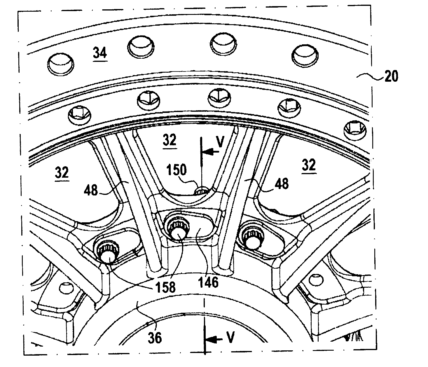
[0061]With reference to FIGS. 3 to 5, there follows a description of a turbomachine of the invention and in particular of the arrangement of the fasteners used for fastening the inner flange 36 to the bearing support 20 of the machine.

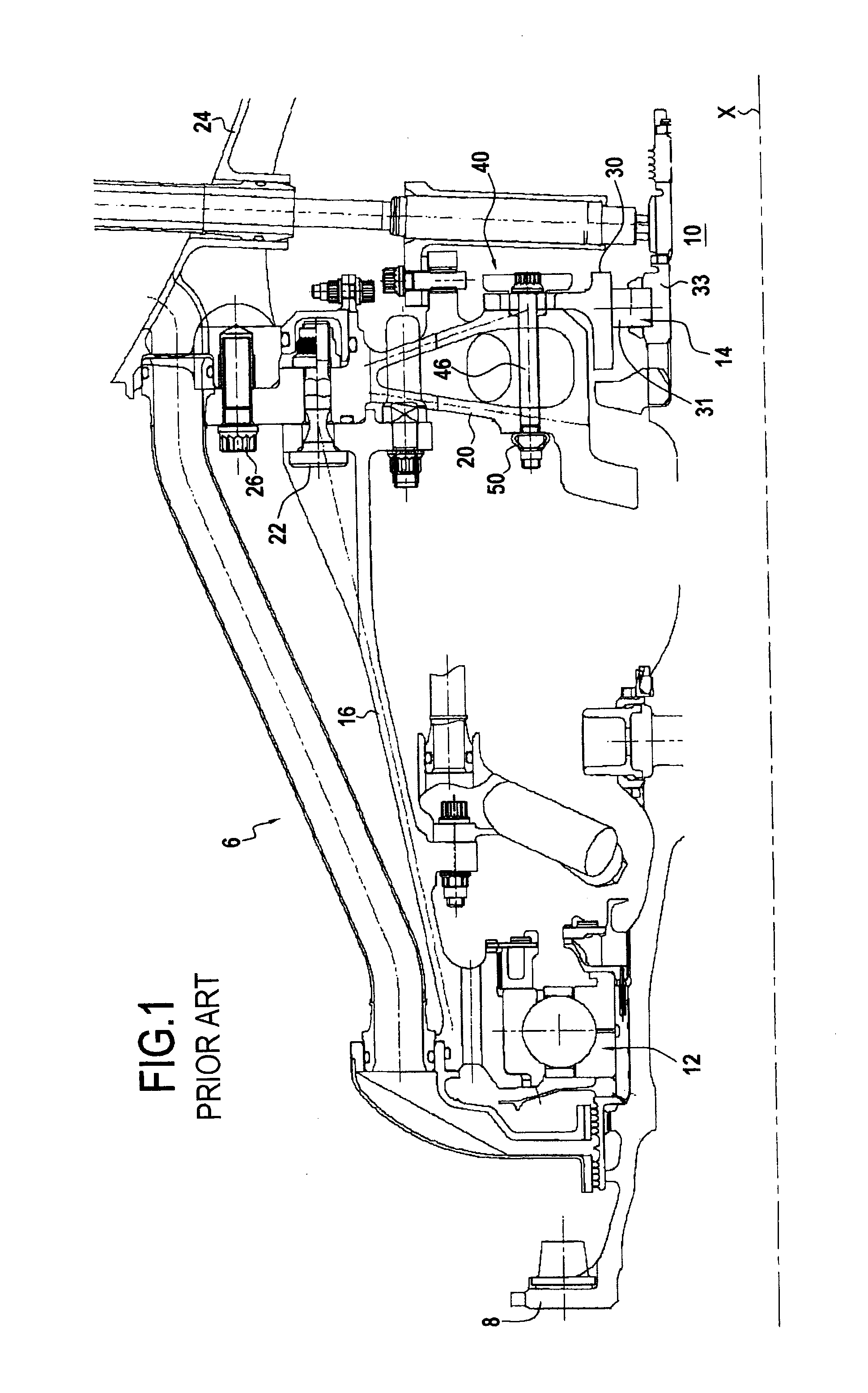
[0062]The general arrangement of the turbomachine is identical to that of the turbomachine 6 described with reference to FIGS. 1 and 2. The improvement provided by the invention relates solely to the fastening of the outer ring 30 to the bearing support 20. In this embodiment, the fastening is provided by means of bolt fasteners 140.

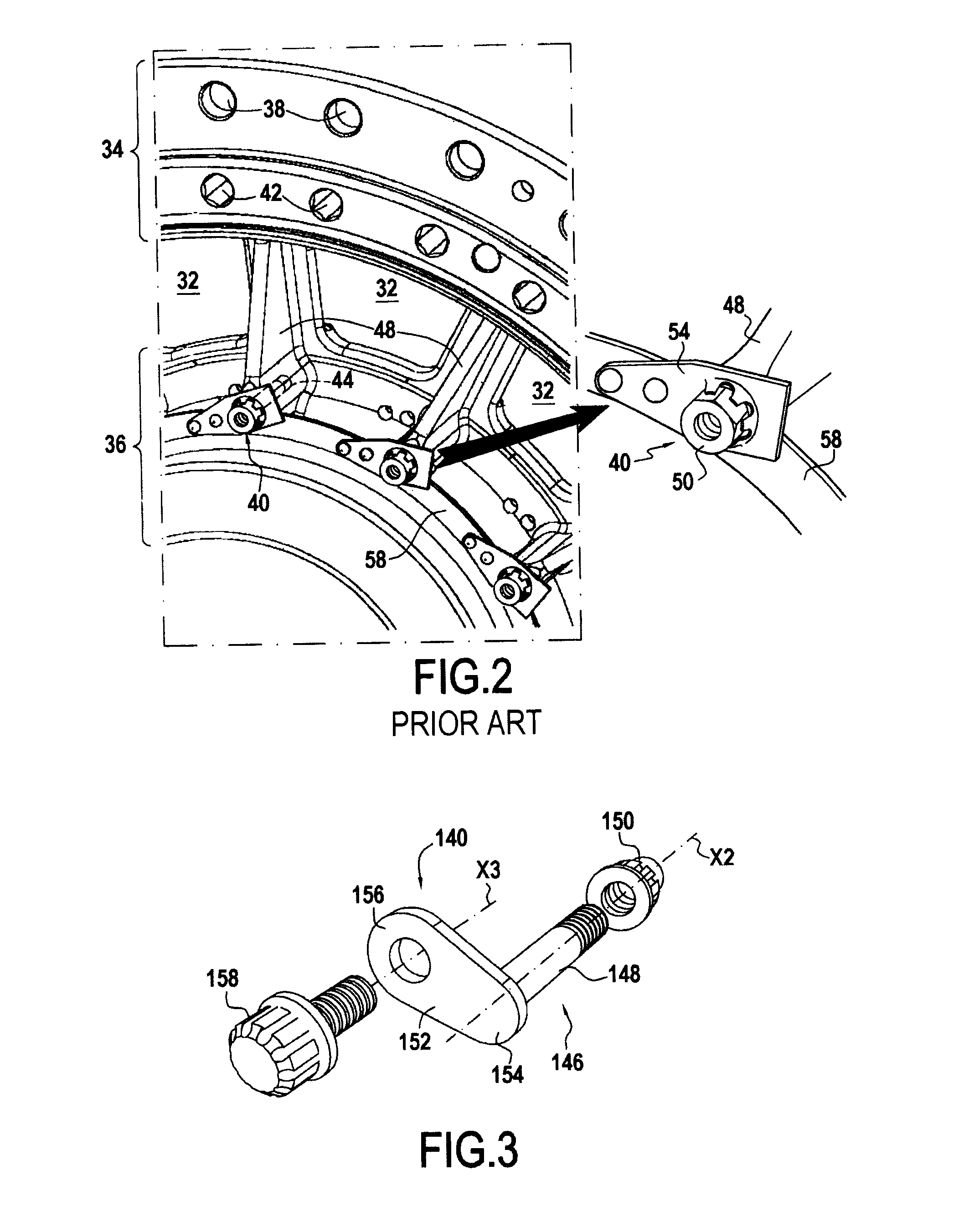
[0063]Like the fasteners 40, each fastener 140 includes a shearable bolt.

[0064]The bearing support 20 includes a ring-shape portion in which the fasteners 140 are fastened.

[0065]Each fastener 140 extends in a through passage formed through the ring-shaped portion of the bearing support 20 and the outer ring 30. Each fastener 140 comprises a bolt 146 and a nut 150. The bolt 146 has a shank 148 of axis X2 and a flat head 152....


PUM

PropertyMeasurementUnit
shapeaaaaaaaaaa
pressureaaaaaaaaaa
conical shapeaaaaaaaaaa

Abstract

A turbomachine including a shaft, a bearing for supporting the shaft and including an outer ring, and a support for said bearing, the support having a flange to which the outer ring is fastened by fasteners; each fastener comprising a fastener bolt and a nut screwed together; the turbomachine also including for each fastener, position-retention means for retaining the bolt, and suitable for retaining the bolt in a position that is stationary relative to the bearing support or the outer ring, even in the absence of the nut. The head of the fastener bolt and the position-retention means may be of small dimensions, thereby enabling the fastening of the flange to the bearing support to be optimized, and in particular enabling the weight of said fastening to be optimized. The invention also provides a method of mounting said bearing of the turbomachine.

Description

FIELD OF THE INVENTION[0001]The invention relates to a turbomachine comprising a rotary shaft held by a bearing having an outer ring; the bearing is supported by a bearing support; and the outer ring of the bearing is fastened to a flange of the bearing support by bolt fasteners.[0002]More precisely, the invention relates to turbomachines of this type in which fastening the outer ring of the bearing to the bearing support is problematic because some of the operations for mounting the bearing are not possible for reasons of insufficient space.BACKGROUND OF THE INVENTION[0003]Because of the structure of the turbomachine and / or its environment and / or its mounting sequence, it can happen that when it is necessary to fasten the outer ring of the bearing to the bearing support, access to one side of the assembly is no longer possible.[0004]The assembly of the outer ring of the bearing and the flange to which it is mounted generally has the overall shape of a disk. Thus, the problematic si...

Claims


Application Information

Patent Timeline
Patent Type & Authority Applications(United States)
IPC IPC(8): F04D29/04B23P15/04
CPCF05B2260/3011F16B41/002F05D2230/60Y10T29/4932F05B2260/301Y02T50/671F01D25/162F16B35/06F16B33/002Y02T50/60
Inventor SERVANT, REGIS EUGENE HENRI
Owner SN DETUDE & DE CONSTR DE MOTEURS DAVIATION S N E C M A
Why Eureka
Try Eureka