
Methods of diagnosing chronic cardiac allograft rejection

a technology of allograft and diagnosis method, which is applied in the field can solve the problems of inability to accurately diagnose cav, etc., and achieve the effect of diagnosing chronic allograft rejection

Inactive Publication Date: 2011-08-04
THE UNIV OF BRITISH COLUMBIA
View PDF1 Cites 5 Cited by
  • Summary
  • Abstract
  • Description
  • Claims
  • Application Information

AI Technical Summary

Benefits of technology

[0046]It is therefore an advantage of some aspects of the present invention to provide a method of diagnosing chronic allograft rejection without a biopsy of the transplanted tissue or organ.
[0052]It is therefore an advantage of some aspects of the present invention to provide a method of diagnosing chronic allograft rejection without a biopsy of the transplanted tissue or organ.

Problems solved by technology

Biopsy results may also be subject to reproducibility and interpretation issues due to sampling errors and inter-observer variabilities, despite the availability of international guidelines such as the Banff schema for grading liver allograft rejection (Ormonde et al 1999.
Although less invasive (imaging) techniques have been developed such as angiography and IVUS for monitoring chronic heart rejection, these alternatives are also susceptible to limitations similar to those associated with biopsies.
However, early diagnosis of CAV is often a difficult task, partly due by the lack of clinical symptoms for ischemia as a result of cardiac denervation.
Acute rejection may be characterized by cellular and humoral insults on the donor tissue, leading to rapid graft dysfunction and failure of the tissue or organ.
Chronic rejection may be characterized by progressive tissue remodeling triggered by the alloimmune response and may lead to gradual neointimal formation within arteries, contributing to obliterative vasculopathy, parenchymal fibrosis and consequently, failure and loss of the graft.
Attempts have been made to reduce the number of biopsies and invasive surveillance techniques per patient, but may be generally unsuccessful, due in part to the difficulty in pinpointing the sites where rejection starts or progresses, and also to the difficulty in assessing tissue without performing the actual biopsy.
Noninvasive surveillance techniques have been investigated, and may provide a reasonable negative prediction of allograft rejection, but may be of less practical utility in a clinical setting (Mehra et al., supra).

Method used


Image

  • Methods of diagnosing chronic cardiac allograft rejection
  • Methods of diagnosing chronic cardiac allograft rejection
  • Methods of diagnosing chronic cardiac allograft rejection

Examples


example 1

[0232]Following normalization and pre-filtering, 25,215 probe sets remained and were included in the subsequent analysis (Step 2) using the training cohort samples. Using robust-test, a total of 106 probe sets were identified as having FDR <10%. A heatmap was constructed for these probe sets to visualize the relative expression levels between CR and S samples (FIG. 4). In addition, over representation analysis was carried out to observe the type of biological and molecular processes encompassed by the differentially expressed genes compare to the rest of the genes present on the microarray. The significantly enriched gene ontology (GO) terms were identified, and those with p-value <0.05 have been summarized in Table 5.

TABLE 5Statistically significant gene ontology terms as identified byenrichment analysis (FatiGo) for genomic expression profiling.Process or responseGeneOntology term (GO term)Immune responseGO: 0006955response to biotic stimulusGO: 0009607humoral immune responseGO: 0...

example 2

Biological Pathways

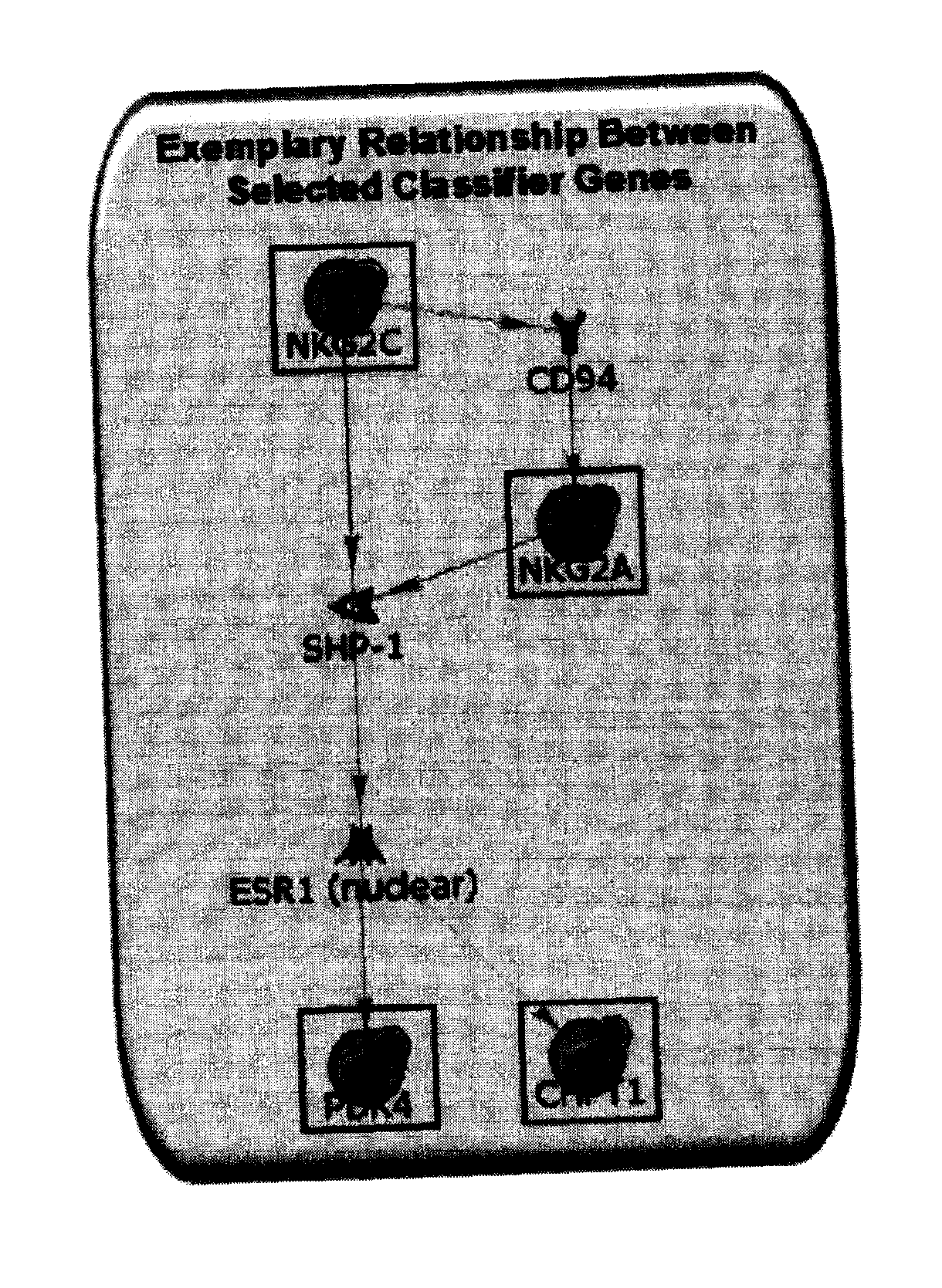
[0235]Using a combination of bioinformatics and literature-based approaches, various pathways have been identified based on selected differentially expressed genes. Without wishing to be bound by theory, interactions between them have also been elucidated in our current results. FIG. 3 illustrates a pathway-based relationship between the biomarkers NKG2A (KLRC1), NKG2C (KLRC2), PDK4 and CHPT1.

[0236]Without wishing to be bound by theory, interactions between the biomarker genes and / or gene products may include:

1. NKG2C (KLRC2)→CD94→NKG2A (KLRC1)

[0237]NKG2C (KLRC2)→CD94 (Ding et al 1999. Scand. J Immunol 49:459-65; Gunturi et al 2004. Immunol. Res 30:29-34)[0238]CD94→NKG2A (KLRC1) (Brooks et al 1997. J Exp Med 185:795-800; Brooks et al 1999. J. Immunol. 162:305-13; Dulphy et al 2002. Int Immunol 14:471-9)

2. NKG2C / NKG2A (KLRC2 / KLRC1)→SHP1→ESR1→PDK4 and CHPT1

[0239]NKG2C / NKG2A (KLRC2 / KLRC1)→SHP1 (Lin Chua et al 2002. Cell Immunol. 219:57-70; Le Drean et al 1998. Eur J ...

example 3

Proteomic Analysis Results

[0242]A total of ˜2500 protein groups codes (PGC) were found in at least one of the 13 samples included in the training cohort. These PGCs were pre-filtered (Step 1)—PGCs which were detected in at least ⅔ of the 7 CR and 6 S samples (i.e., 5 CR and 6 S samples) were used for further analysis. Statistical analysis identified 14 of the 129 analyzed proteins with differential relative concentrations with p-value <0.05 (Step 3). A heatmap was constructed to visualize the performance of these significant PGCs in discriminating CR from S samples (FIG. 5). Over representation analysis was also carried out to explore the biological and molecular functions of all the proteins belonging to these protein group codes. The significantly enriched GO terms with p-value <0.05 are shown in Table 7.

TABLE 7Statistically significant gene ontology terms as identified by enrichmentanalysis (FatiGo) for proteomic expression profiling.Process or responseGeneOntology term (GO term)...


PUM

PropertyMeasurementUnit
temperatureaaaaaaaaaa

Abstract

The present invention relates to methods of diagnosing chronic rejection of a cardiac allograft using genomic expression profiling, proteomic expression profiling, or a combination of genomic and proteomic expression profiling.

Description

[0001]This application claims priority benefit of U.S. Provisional applications 61 / 071,056, filed Apr. 10, 2008; and U.S. 61 / 157,166, filed Mar. 3, 2009, both of which are herein incorporated by reference.FIELD OF INVENTION[0002]The present invention relates to methods of diagnosing chronic rejection of a cardiac allograft using genomic expression profiling, proteomic expression profiling, or a combination of genomic and proteomic expression profiling.BACKGROUND OF THE INVENTION[0003]Transplantation is considered the primary therapy for patients with end-stage vital organ failure. While the availability of immunosuppressants such as cyclosporine and Tacrolimus has improved allograft recipient survival and wellbeing, identification of rejection of the allograft as early and as accurately as possible, and effective monitoring and adjusting immunosuppressive medication doses is still of primary importance to the continuing survival of the allograft recipient.[0004]Rejection of an allog...

Claims


Application Information

Patent Timeline
Patent Type & Authority Applications(United States)
IPC IPC(8): C40B30/04C12Q1/68G01N33/68G01N33/566
CPCC12Q1/6883C12Q2600/158G01N33/505G01N2800/32G01N33/6848G01N33/6893G01N2800/245G01N33/6842C12Q1/6844C40B30/04
Inventor MCMANUS, BRUCEHOLLANDER, ZSUZSANNALIN, DAVIDBALSHAW, ROBERTMCMASTER, ROBERTKEOWN, PAULFREUE, GABRIELA COHENWILSON-MCMANUS, JANETNG, RAYMOND
Owner THE UNIV OF BRITISH COLUMBIA
Learn More