Clutch controlling apparatus

Active Publication Date: 2011-08-04
HONDA MOTOR CO LTD
View PDF37 Cites 24 Cited by
  • Summary
  • Abstract
  • Description
  • Claims
  • Application Information

AI Technical Summary

Benefits of technology

[0020]According to the third characteristic, if the elapsed time after the shift change of the clutch is started exceeds the predetermined time, then the degree by which the correction in the clutch engagement direction is carried out is increased. Therefore, even if correction based on the input/output power ratio is carried out, if the time before the shift change is completed by engagement of the clutch is longer, then the driving amount of the clutch can be increased to complete the shift change quickly.
[0021]According to the fourth characteristic, the predetermined time has a value obtained by multiplying the shift change completion time Th by the predetermined coefficient, and the clutch shift change torque is calculated by subtracting the engine torque estimated value from the target clutch capacity upon starting of the shift change. Then, the clutch shift change torque is applied to the data table which represents the relationship between the clutch shift change torque and the shift variation ΔNe on shift change which is a variation amount of rotation of the engine during shift change to derive the shift variation ΔNe on shift change. Then, rotation of the engine where the shift change stage after the shift change is established while the vehicle speed at present is maintained is subtracted from rotation of the engine upon starting of the shift change to calculate the clutch slip rotation. Then, the clutch slip rotation is divided by the shift variation ΔNe on shift change to calculate the shift change completion time. Therefore, after variation estimation of rotation of the engine is carried out in response to an engine torque transmission state at present, the shift change completion timing with respect to the variation of rotation of the engine at present can be estimated, and no uncomfortable feeling is caused by the correction of the clutch.
[0022]According to the fifth characteristic, the correction amount is increased in response to the elapsed time from the point of time at which the elapsed time after the shift change is started exceeds the predetermined time. Therefore, engagement of the clutch is increased quickly after the estimated time of the shift change completion elapses.
[0023]According to the sixth characteristic, the degree by which the target control amount of the clutch is set individually for each shift change stage of the shift change transmission, and is set such that the degree by which the target control amount is corrected increases in shorter time

Problems solved by technology

However, if it is tried to use the technique described in Patent Document 1 to detect an engagement state of a clutch, particularly a clutch slip state which causes a racing phenomenon of an engine, then there is the possibility that, for example, when a shift up operation is carri

Method used


Image

  • Clutch controlling apparatus
  • Clutch controlling apparatus
  • Clutch controlling apparatus

Examples


Example

[0063]In the following, a preferred embodiment of the present invention is described in detail with reference to the drawings. In the following description, unless otherwise specified, the directions such as forward, backward, leftward and rightward directions are same as those of a vehicle. Further, an arrow mark FR in the figures indicates the forward direction of the vehicle and an arrow mark LH indicates the leftward direction of the vehicle while an arrow mark UP indicates an upward direction of the vehicle.

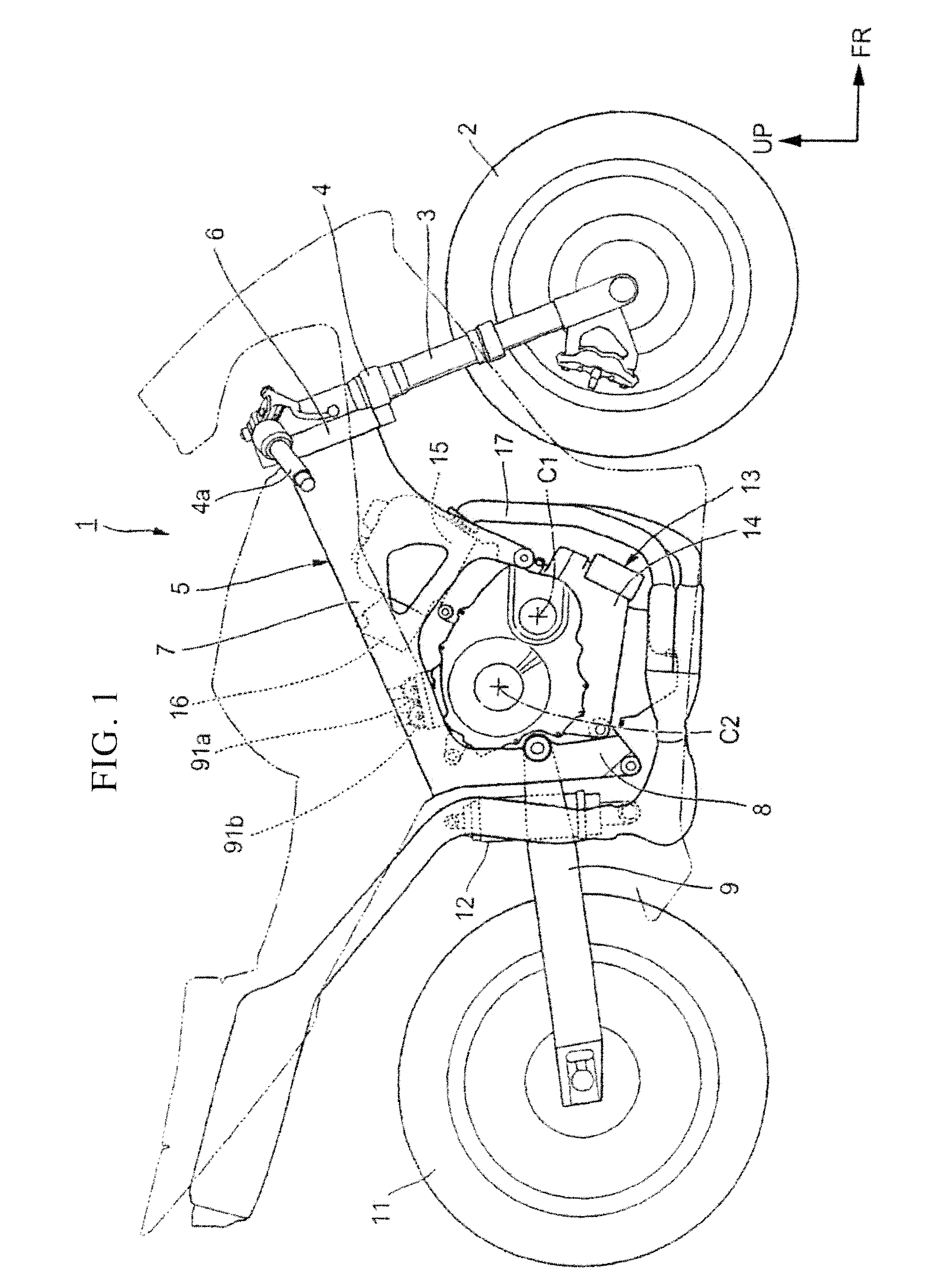
[0064]FIG. 1 is a side elevational view of a vehicle such as motorcycle 1 as a saddle type vehicle to which a clutch controlling apparatus according to the present invention is applied. A front fork 3 for supporting a front wheel 2 for rotation thereon is supported at an upper portion thereof for steering motion on a head pipe 6 at a front end portion of a vehicle body frame 5 through a steering stem 4. A steering handle bar 4a is attached at an upper portion of the steering...


PUM


Abstract

A clutch controlling apparatus includes a shift change transmission having a plurality of gear trains between a main shaft on an input side and a countershaft on an output side. A clutch controls transmission of power between the shift change transmission and an engine between engagement an disengagement. The clutch controlling apparatus automatically controls the clutch upon shift change of the shift change transmission. An input power ratio is calculated as a ratio between a rotation of the engine and a rotation of the countershaft. If the input/output power ratio exceeds a predetermined value in a direction of a rise of the rotation of the engine during shift change of the shift change transmission, a target control amount of the clutch is corrected in a clutch engagement direction.

Description

BACKGROUND[0001]This invention relates to a clutch controlling apparatus, and particularly to a clutch controlling apparatus which uses an actuator to control a clutch between engagement and disengagement.DESCRIPTION OF THE RELATED ART[0002]Conventionally, a clutch controlling apparatus is known wherein a clutch for transmitting rotational driving power of a power source by frictional force is controlled between engagement and disengagement by an actuator. In such a clutch controlling apparatus as just described, in order to allow the clutch to exert optimum frictional force to implement smooth engagement control, feedback control based on the engagement state of the clutch is preferably executed.[0003]Patent Document 1 (Japanese Patent Publication No. Hei. 6-89793) discloses a technique of setting, in advance, a reference value for rotation of an engine with respect to an engagement amount of a clutch and controlling engagement of the clutch so as to make rotation of the engine at ...

Claims


Application Information

Patent Timeline
IPC IPC(8): F16D48/06
CPCF16D48/066F16D2500/1026F16H61/16F16D2500/3082F16D2500/5046F16D2500/3067
Inventor NEDACHI, YOSHIAKIKOJIMA, HIROYUKI
Owner HONDA MOTOR CO LTD
Why Eureka
Try Eureka