Phase-Modulated RF Power for Plasma Chamber Electrode

a plasma chamber electrode and phase-modulated technology, applied in the field of phase-modulated rf power for plasma chamber electrodes, can solve problems such as spatial non-uniformity

Inactive Publication Date: 2011-08-11
APPLIED MATERIALS INC
View PDF0 Cites 51 Cited by
  • Summary
  • Abstract
  • Description
  • Claims
  • Application Information

AI Technical Summary

Benefits of technology

[0010]In a second embodiment or aspect of the invention, at least two of the RF power signals have time-varying phase offsets relative to the reference RF signal that are distinct functions of time which are not required to be periodic. An additional RF power signal having a lower RF frequency also is coupled to the electrode of the plasma chamber. Advantageously, the RF power at the lower frequency can reinforce the plasma density at one or more locations where the instantaneous or time-averaged electric field produced by the RF power at the higher reference frequency is minimum.

Problems solved by technology

If any dimension of the electrode is greater than approximately one-tenth the wavelength of the RF power in the plasma, the plasma density, and hence the plasma fabrication process being performed on the workpiece, typically will suffer spatial non-uniformity if the RF power is coupled to only a single point on the electrode.

Method used


Image

  • Phase-Modulated RF Power for Plasma Chamber Electrode
  • Phase-Modulated RF Power for Plasma Chamber Electrode
  • Phase-Modulated RF Power for Plasma Chamber Electrode

Examples


first embodiment

[0046] or first aspect of the invention summarized in the above “Summary of the Invention”, at least all but one of the phase modulation functions Φ1(t) is a distinct, periodic function of time characterized by a repetition period. In other words, Φi(t)=Φi(t+1 / Fi) and, where (1 / Fi) is the repetition period of the i-th phase modulation function. We refer to Fi as the “phase modulation repetition frequency” (or simply the “phase modulation frequency”) of the i-th phase modulation function Φi(t).

[0047]The reason that one of the phase modulation functions is not required to be a periodic function of time is that the spatial distribution of the RF electric field produced by the RF power signals is a function of the phases of the RF power signals relative to each other. If one of the RF power signals has a constant or zero phase offset relative to the reference RF signal, each of the other RF power signals will still have a time-varying, periodic phase offset relative to said one RF power...

second embodiment

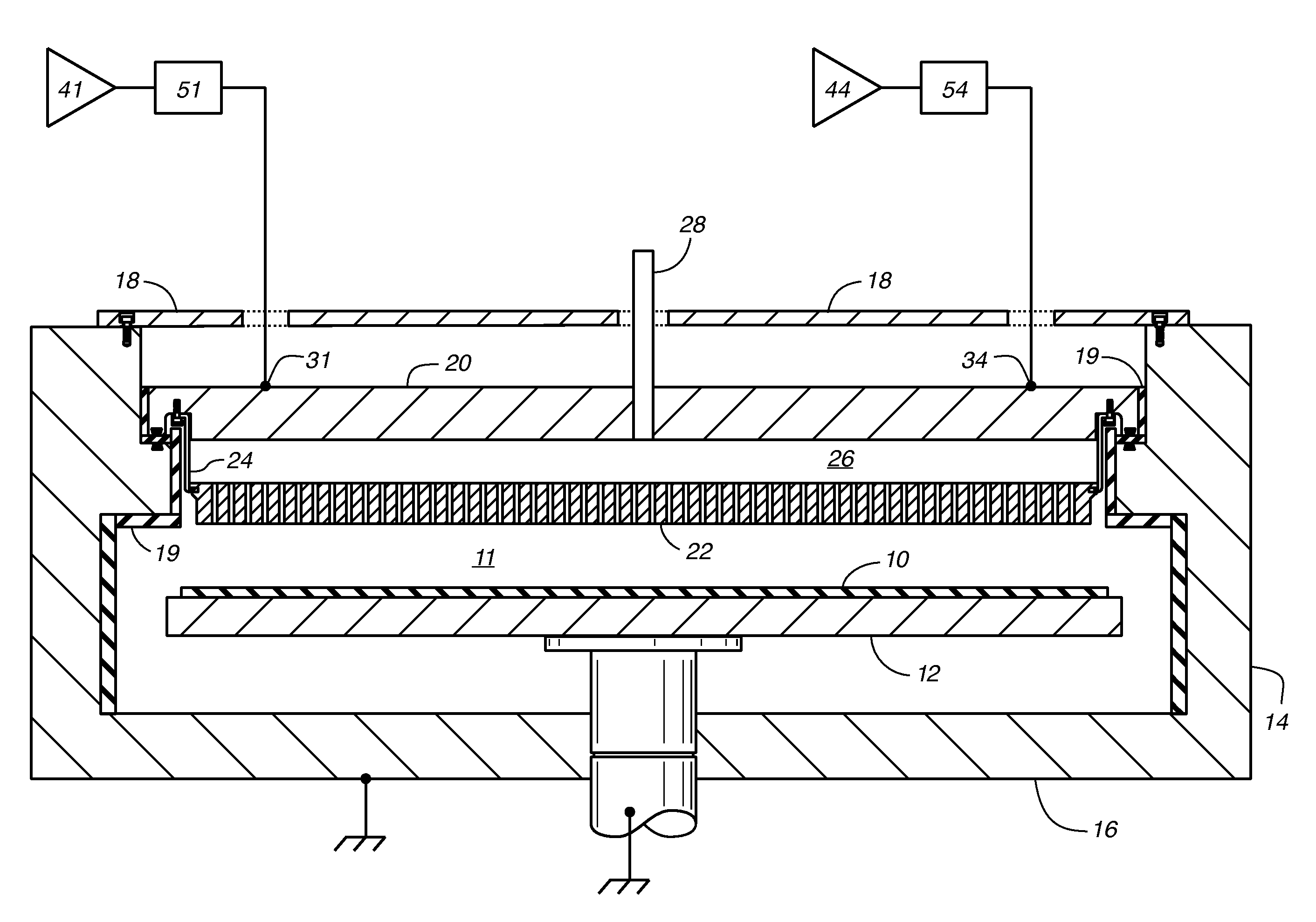
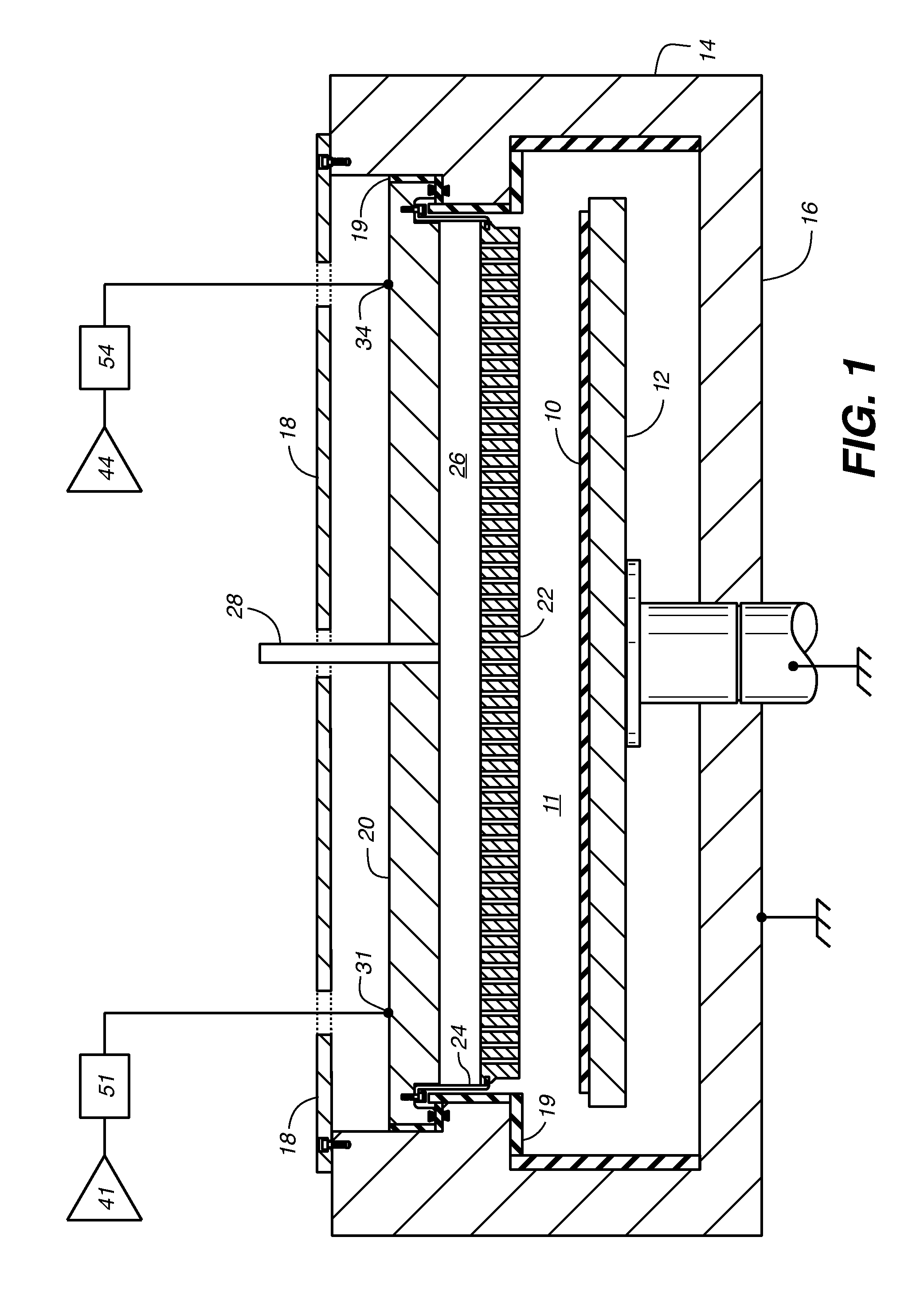
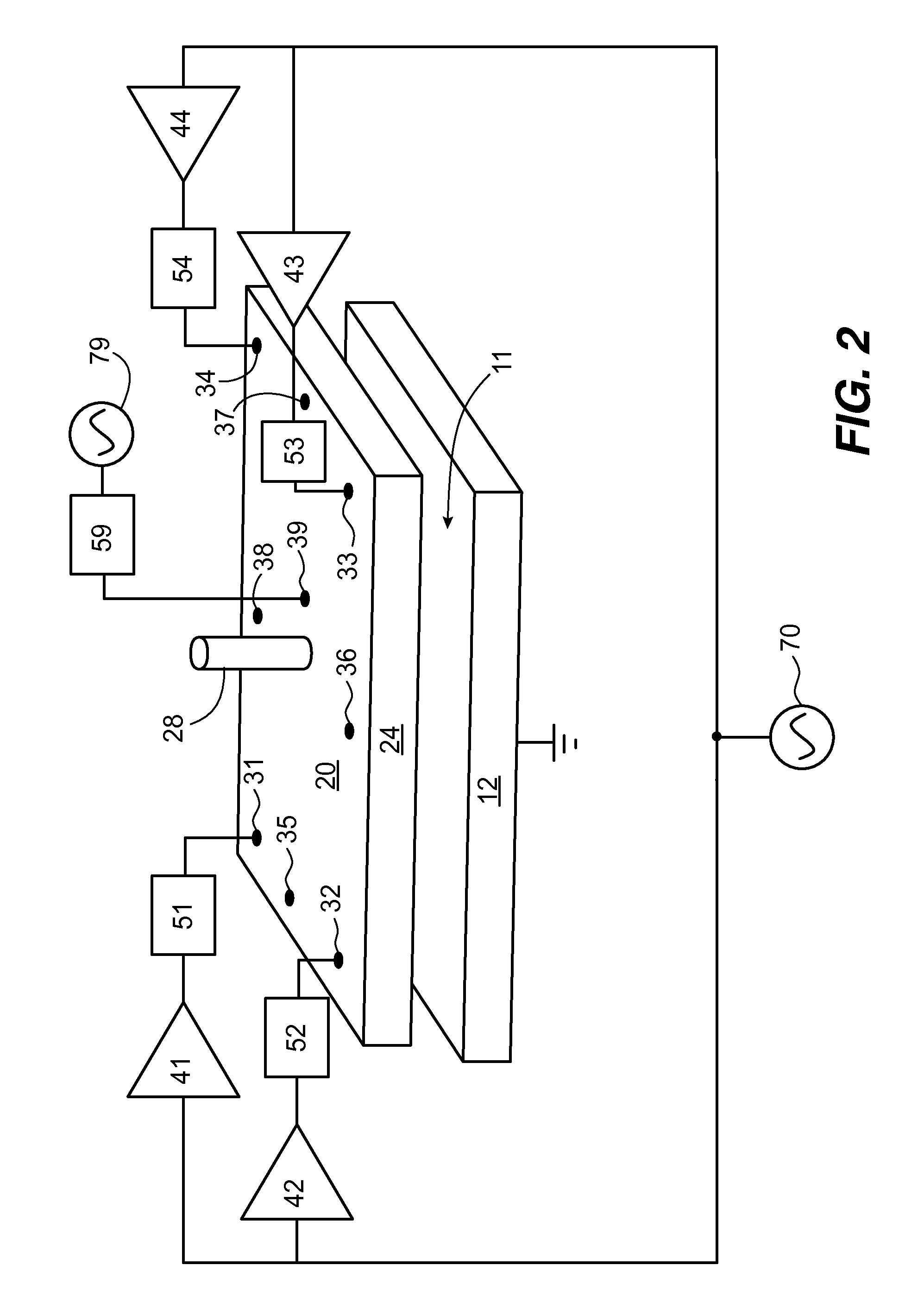
[0067]The second embodiment or second aspect of the invention summarized in the above “Summary of the Invention” includes an additional RF power source 79 that outputs an RF power signal having a second RF frequency that is lower than the reference RF frequency f. A lower frequency RF power signal generally produces an electric field spatial distribution having more widely spaced instantaneous peaks and minimums in comparison with a higher frequency RF power signal. Therefore, by coupling lower frequency RF power to the plasma, the additional RF power source can increase the plasma density at one or more locations of instantaneous or time-averaged minimums in the interference pattern produced by the multiple RF power sources 41-44 at the higher first frequency. In the absence of such lower frequency additional RF power source 79, we found that instantaneous minimums could possibly make the plasma less uniform, depending on the operating conditions of the plasma chamber.

[0068]The out...


PUM

PropertyMeasurementUnit
RF poweraaaaaaaaaa
RF frequencyaaaaaaaaaa
first phase offsetaaaaaaaaaa

Abstract

A plurality of RF power signals have the same RF frequency as a reference RF signal and are coupled to respective RF connection points on an electrode of a plasma chamber. At least three of the RF connection points are not collinear. At least two of the RF power signals have time-varying phase offsets relative to the reference RF signal that are distinct functions of time. Such time-varying phase offsets can produce a spatial distribution of plasma in the plasma chamber having better time-averaged uniformity than the uniformity of the spatial distribution at any instant in time.

Description

CROSS REFERENCE TO RELATED APPLICATIONS[0001]This patent application claims the benefit of U.S. Provisional Application No. 61 / 294,128 filed Jan. 12, 2010; U.S. Provisional Application No. 61 / 294,468 filed Jan. 12, 2010; and U.S. Provisional Application No. 61 / 352,817 filed Jun. 8, 2010.TECHNICAL FIELD[0002]The invention relates generally to coupling RF power to an electrode of a plasma chamber used to perform plasma processes for fabricating electronic devices such as semiconductors, displays, solar cells, and solid state light emitting devices. The invention relates more specifically to coupling RF power to different points on the electrode with different time-varying phase offsets, whereby the uniformity of such plasma processes typically can be improved.BACKGROUND ART[0003]Plasma chambers commonly are used to perform plasma processes for fabricating electronic devices such as semiconductors, displays and solar cells. Such plasma fabrication processes include chemical vapor depos...

Claims


Application Information

Patent Timeline
Patent Type & Authority Applications(United States)
IPC IPC(8): C23C16/509
CPCC23C16/509H05H1/46H01J37/32091H01J37/32082
Inventor HAMMOND, IV, EDWARD P.TANAKA, TSUTOMUBOITNOTT, CHRISTOPHERKUDELA, JOZEF
Owner APPLIED MATERIALS INC
Why Eureka
Try Eureka