Welding gun
- Summary
- Abstract
- Description
- Claims
- Application Information
AI Technical Summary
Benefits of technology
Problems solved by technology
Method used
Image

Examples
first embodiment
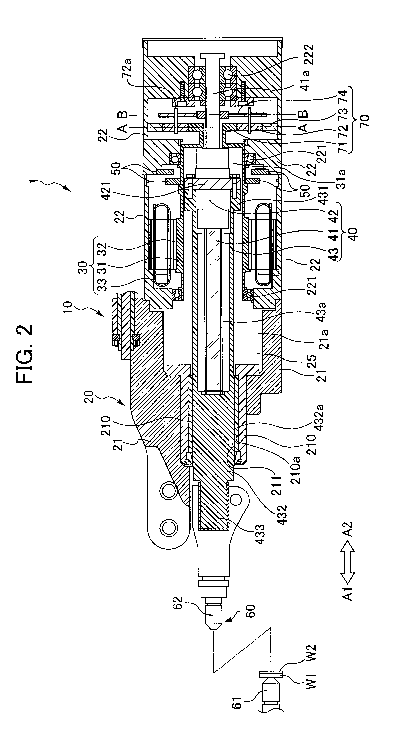
[0033]FIG. 2 is a longitudinal sectional view of the electric spot welding gun 1 according to the present invention.
[0034]Hereinafter, each configuration of the electric spot welding gun 1 will be explained.
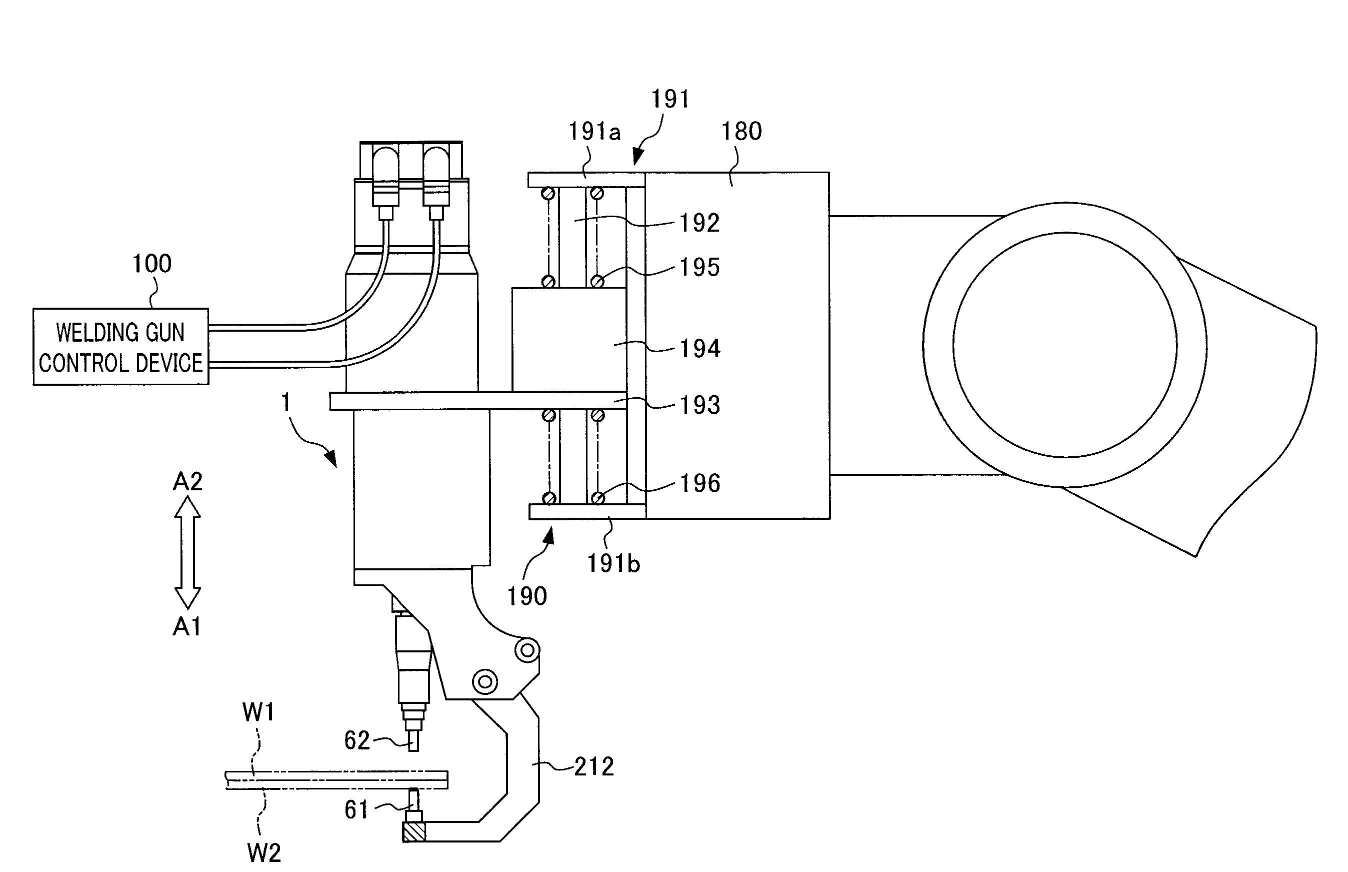
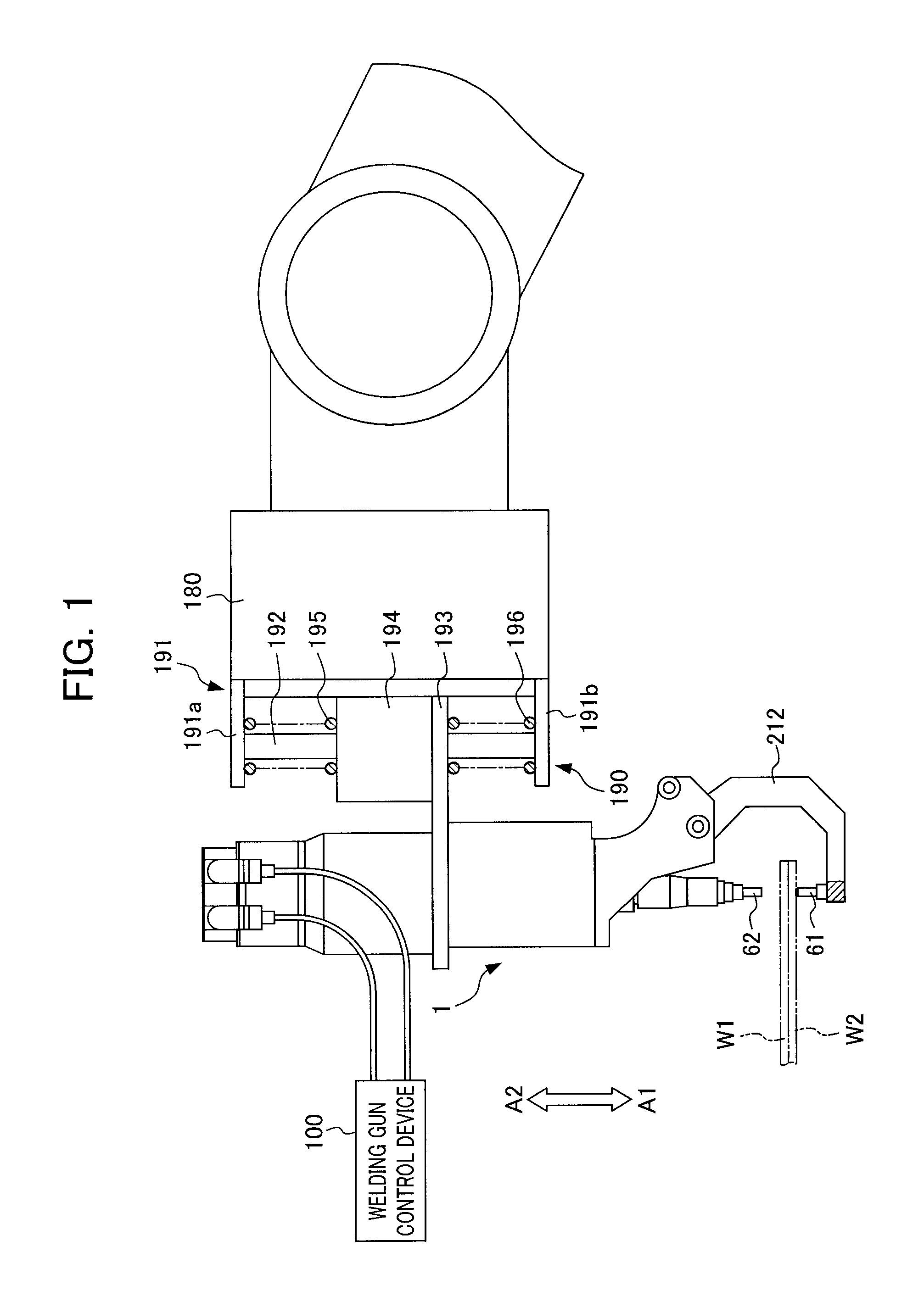
[0035]The electric spot welding gun 1 includes a servo motor 10 having a motor housing 20, motor 30 and a hollow encoder 50, a feed screw mechanism 40, electrode tips 60, and a planetary gear reduction mechanism 70.
[0036]The planetary gear reduction mechanism 70 is coupled to the servo motor 10 at a base end side of the servo motor 10 (arrow A2 side shown in FIG. 2).
[0037]The feed screw mechanism 40 is coupled to the planetary gear reduction mechanism 70 at a base end side of the feed screw mechanism 40 (arrow A2 side shown in FIG. 2).
[0038]One of the electrode tips 60 is provided to a leading end side of the feed screw mechanism (arrow A1 side shown in FIG. 2).
[0039]The servo motor 10 includes a motor housing 20 that forms a main body of the electric spot welding gun 1 and accom...
second embodiment
[0077]Next, an electric spot welding gun 1 according to the present invention will be explained.
[0078]FIG. 5 is a longitudinal sectional view of the electric spot welding gun 1 according to the second embodiment of the present invention.
[0079]FIG. 6 is a cross-sectional view along the line C-C in FIG. 5.
[0080]FIG. 7 is a cross-sectional view along the line D-D in FIG. 5.
[0081]FIG. 8 is a cross-sectional view along the line E-E in FIG. 5.
[0082]As shown in FIG. 5, a planetary gear reduction mechanism 80 is used in the second embodiment in place of the planetary gear reduction mechanism 70 of the first embodiment. Therefore, except for the planetary gear reduction mechanism 80, configurations of the second embodiment are assigned the same reference symbols in the drawings due to being substantially the same as the first embodiment, and explanations thereof are omitted.
[0083]The planetary gear reduction mechanism 80 includes a sun gear 81 that is formed to couple with the hollow rotor 3...
PUM
| Property | Measurement | Unit |
|---|---|---|
| Size | aaaaa | aaaaa |
Abstract
Description
Claims
Application Information
 - Generate Ideas
- Intellectual Property
- Life Sciences
- Materials
- Tech Scout
- Unparalleled Data Quality
- Higher Quality Content
- 60% Fewer Hallucinations
Browse by: Latest US Patents, China's latest patents, Technical Efficacy Thesaurus, Application Domain, Technology Topic, Popular Technical Reports.
© 2025 PatSnap. All rights reserved.Legal|Privacy policy|Modern Slavery Act Transparency Statement|Sitemap|About US| Contact US: help@patsnap.com