Solder Interconnect with Non-Wettable Sidewall Pillars and Methods of Manufacture

Active Publication Date: 2011-08-11
GLOBALFOUNDRIES US INC
View PDF27 Cites 24 Cited by
  • Summary
  • Abstract
  • Description
  • Claims
  • Application Information

AI Technical Summary

Benefits of technology

[0006]In a first aspect of the invention, a method comprises forming a nickel or nickel alloy pillar on an underlying surface. Th

Problems solved by technology

However, copper pillar based solder connectors are relatively expensive to fabricate and also difficult to prevent the solder from wetting to the copper pillar sidewall.
This can cause bridging between a

Method used


Image

  • Solder Interconnect with Non-Wettable Sidewall Pillars and Methods of Manufacture
  • Solder Interconnect with Non-Wettable Sidewall Pillars and Methods of Manufacture
  • Solder Interconnect with Non-Wettable Sidewall Pillars and Methods of Manufacture

Examples


Embodiment Construction

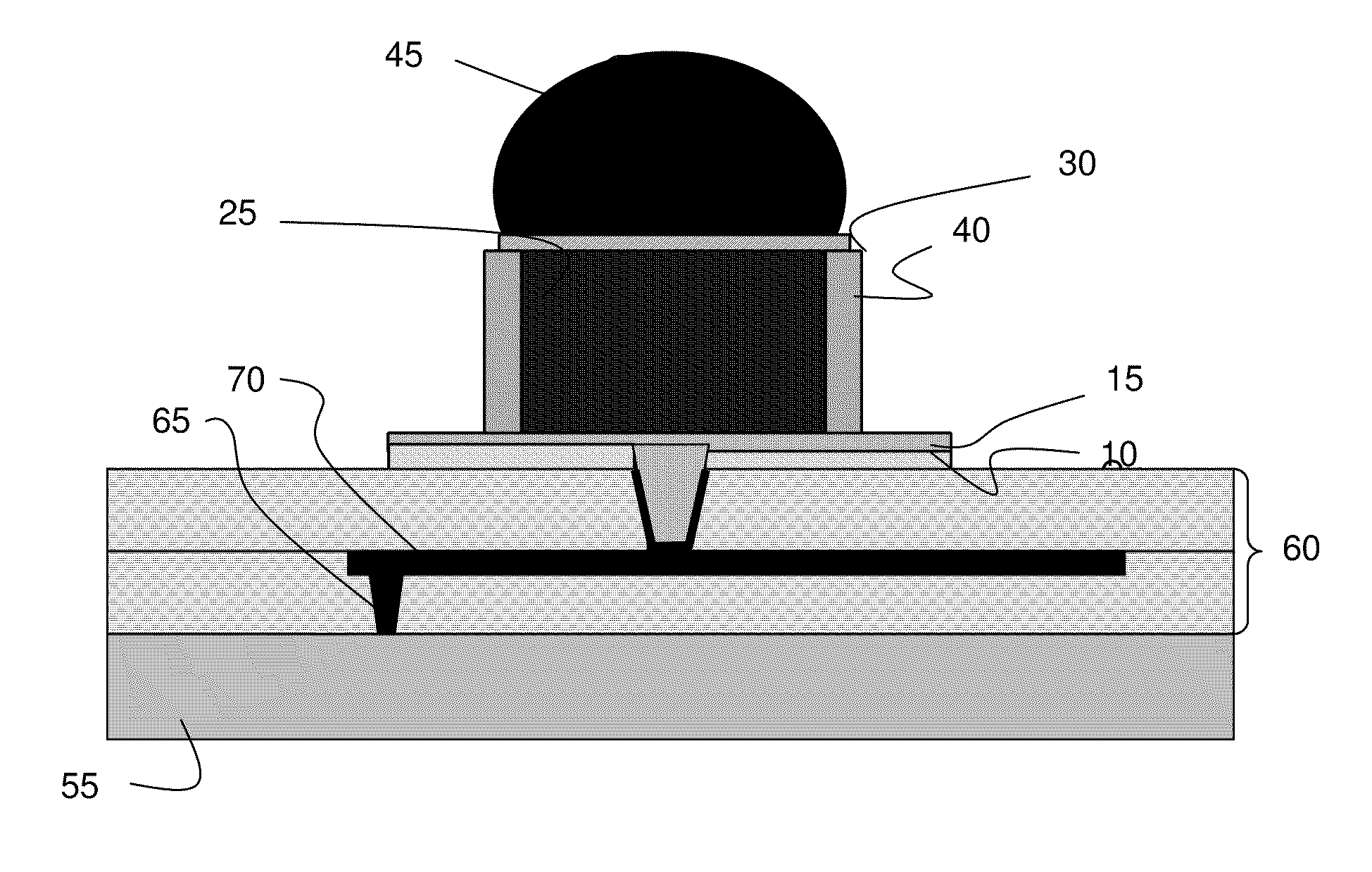
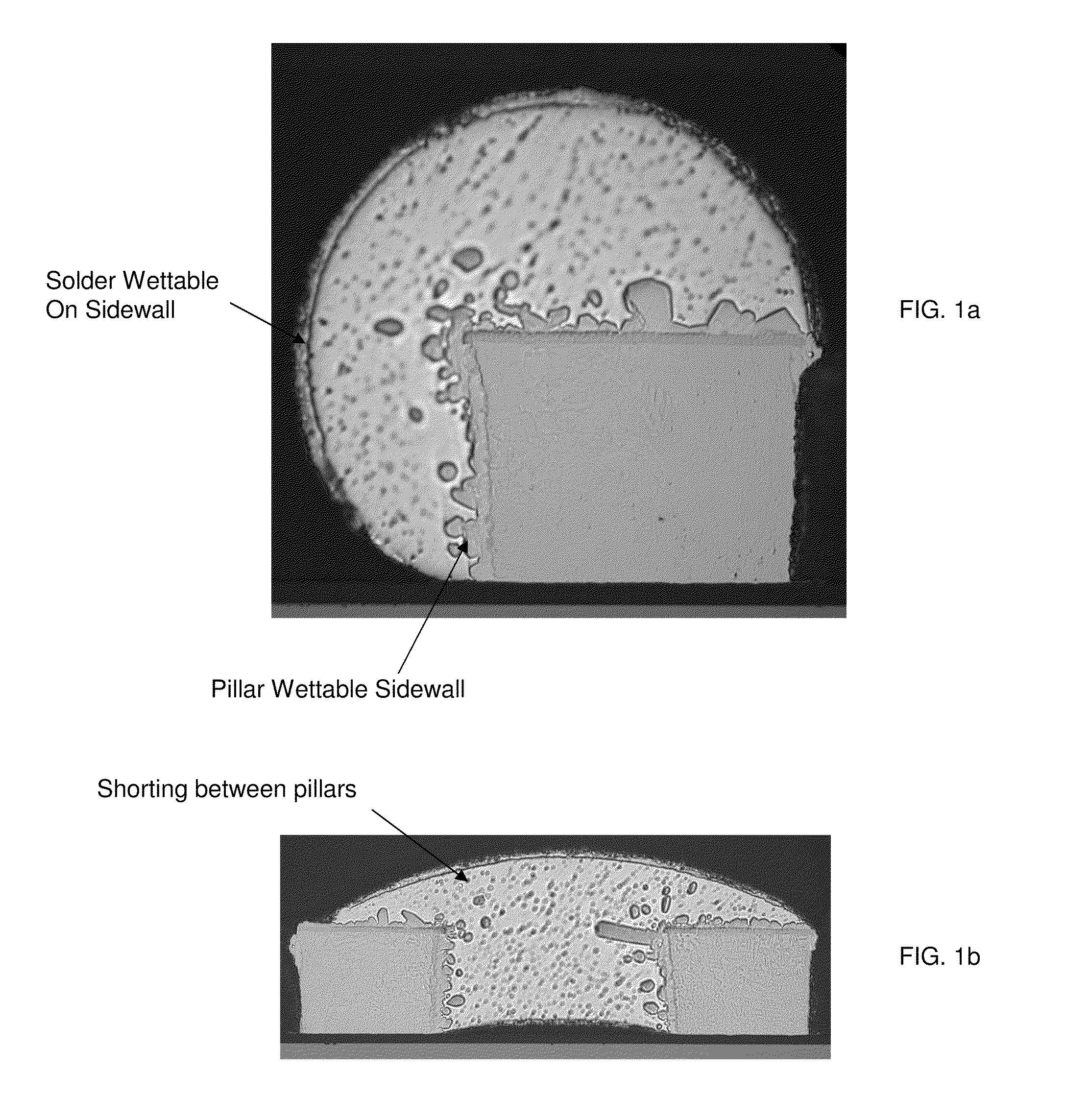
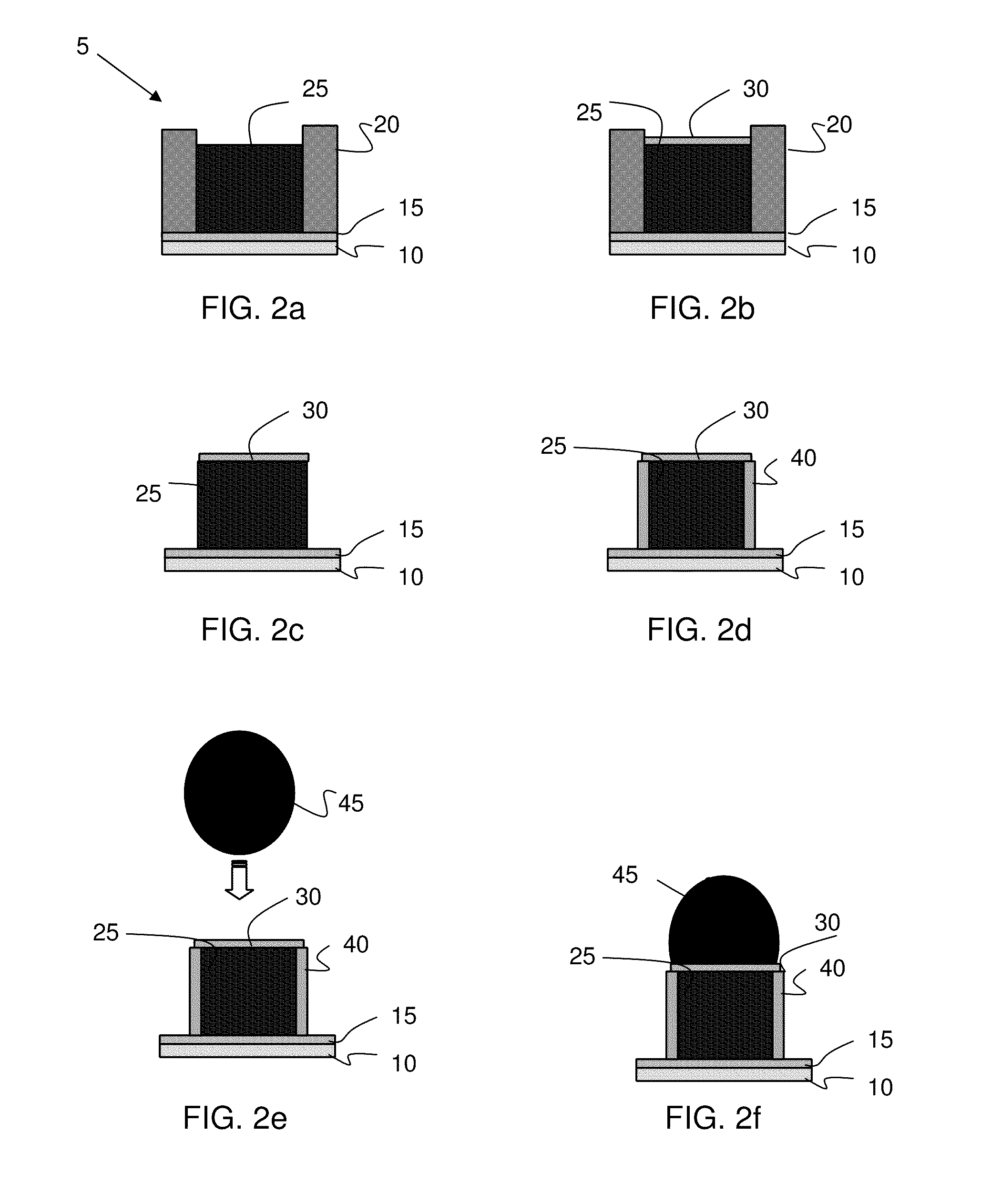
[0017]The invention relates to semiconductor structures and methods of manufacture and, more particularly, to solder interconnect structures with non-wettable sidewall(s) and methods of manufacturing the same. More specifically, the present invention utilizes a nickel or nickel alloy pillar (compared to a copper pillar) to enable post processes that prevent solder wetting. In this way, the present invention improves device performance with a significant reduction in device shorting between connections, as well as allows denser pitch of interconnects to be formed on the device surface.

[0018]In embodiments, the present invention utilizes a nickel or nickel alloy pillar with a modified surface such as, for example, an oxide or nitride sidewall to further enhance the advantages of the present invention. For example, the oxide or nitride sidewall will prevent wetting of the solder. Nickel oxides produce a uniform protective coating that protects the sidewalls of the pillar and alters the...


PUM


Abstract

A solder interconnect structure is provided with non-wettable sidewalls and methods of manufacturing the same. The method includes forming a nickel or nickel alloy pillar on an underlying surface. The method further includes modifying the sidewall of the nickel or nickel alloy pillar to prevent solder wetting on the sidewall.

Description

FIELD OF THE INVENTION[0001]The invention relates to semiconductor structures and methods of manufacture and, more particularly, to solder interconnect structures with non-wettable sidewalls and methods of manufacturing the same.BACKGROUND OF THE INVENTION[0002]Copper pillar is a chip-to-package interconnect technology that is entering the market. The advantages in copper lie in the extendability to finer pitch and the superior electromigration (EM) performance compared to conventional solder C4's. The copper pillar provides the enhanced EM performance but increases the die stress for chip-to-chip and chip-to-wafer joins (i.e., 3D applications). The finer pitch is due to its vertical sidewalls.[0003]In copper pillar technology, a small amount of solder is still required to connect the copper pillars on the chips to the pad on the substrate. However, copper pillar based solder connectors are relatively expensive to fabricate and also difficult to prevent the solder from wetting to th...

Claims


Application Information

Patent Timeline
IPC IPC(8): H01L23/498H01L21/768
CPCH01L23/49811H01L2224/0401H01L24/13H01L24/16H01L2224/05647H01L2224/05655H01L2224/05666H01L2224/11334H01L2224/1146H01L2224/1147H01L2224/1182H01L2224/119H01L2224/13017H01L2224/13018H01L2224/13083H01L2224/13084H01L2224/13101H01L2224/13144H01L2224/13147H01L2224/13155H01L2224/13565H01L2224/1357H01L2224/13687H01L2924/01029H01L2924/01079H01L2924/01082H01L2924/3841H01L24/11H01L2224/10126H01L2924/01327H01L2924/014H01L2924/01074H01L2924/01033H01L2924/01019H01L2924/01006H01L2924/01005H01L2924/00014H01L2924/01024H01L2924/01026H01L2924/01032H01L2924/14H01L2224/1308H01L2924/384H01L2924/00012H01L2924/00
Inventor ARVIN, CHARLES L.BEZAMA, RASCHID J.DAUBENSPECK, TIMOTHY H.GAMBINO, JEFFREY P.MUZZY, CHRISTOPHER D.QUESTAD, DAVID L.SAUTER, WOLFGANGSULLIVAN, TIMOTHY D.SUNDLOF, BRIAN R.
Owner GLOBALFOUNDRIES US INC
Why Eureka
Try Eureka