Integrated on-time extension for non-dissipative bleeding in a power supply

a power supply and on-time extension technology, applied in the field of switched-mode power supply controllers, can solve the problems of led lamp color shifting, triac dimmer is likely to produce unacceptable, and the light emitting diode (led) lamp is likely to be affected by the effect of dimmer color chang

Inactive Publication Date: 2011-08-11
POWER INTEGRATIONS INC
View PDF10 Cites 61 Cited by
  • Summary
  • Abstract
  • Description
  • Claims
  • Application Information

AI Technical Summary

Problems solved by technology

Although phase angle dimming works well with incandescent lamps that receive the altered ac line voltage directly, it typically creates problems for light emitting diode (LED) lamps.
Unless a power supply for an LED lamp is specially designed to recognize and respond to the voltage from a triac dimmer circuit in a desirable way, a triac dimmer is likely to produce unacceptable results such as flickering of the LED lamp, flashing of the LED lamp at high phase angles, and color shifting of the LED lamp.
Another difficulty in using triac dimming circuits with LED lamps comes from a characteristic of the triac itself.
However, the low current taken by efficient power supplies which drive LED lamps from the ac power source may not be enough to keep a triac conducting for the expected portion of the ac line period.
However, use of the conventional bleeder circuit external to the conventional power supply controller requires the use of extra components with associated penalties in cost and efficiency.
However, due to the non-linear loading that many switching power supplies present to the ac power source, the wave shape of the current drawn from the ac power source by the power supply is non-sinusoidal and / or out of phase with the ac input voltage.
This leads to increased losses in the ac mains distribution system and, in many parts of the world, is now the subject of legislative or voluntary requirements that force power supply manufacturers to ensure the input current drawn by the power supply is sinusoidal and in phase with the ac input voltage waveform.
However, as stated above, the use of a conventional bleeder circuit external to the conventional power supply controller requires the use of extra components with associated penalties in cost and efficiency.

Method used


Image

  • Integrated on-time extension for non-dissipative bleeding in a power supply
  • Integrated on-time extension for non-dissipative bleeding in a power supply
  • Integrated on-time extension for non-dissipative bleeding in a power supply

Examples


Embodiment Construction

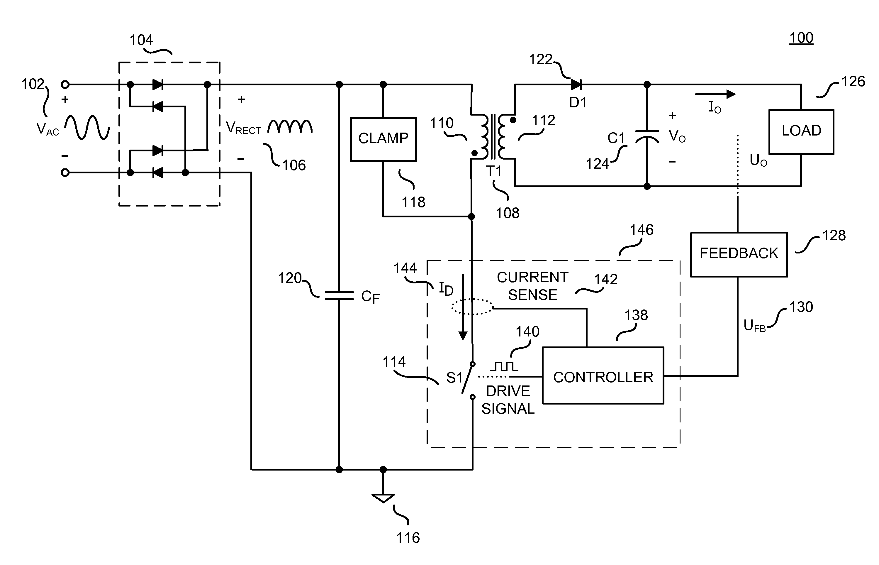
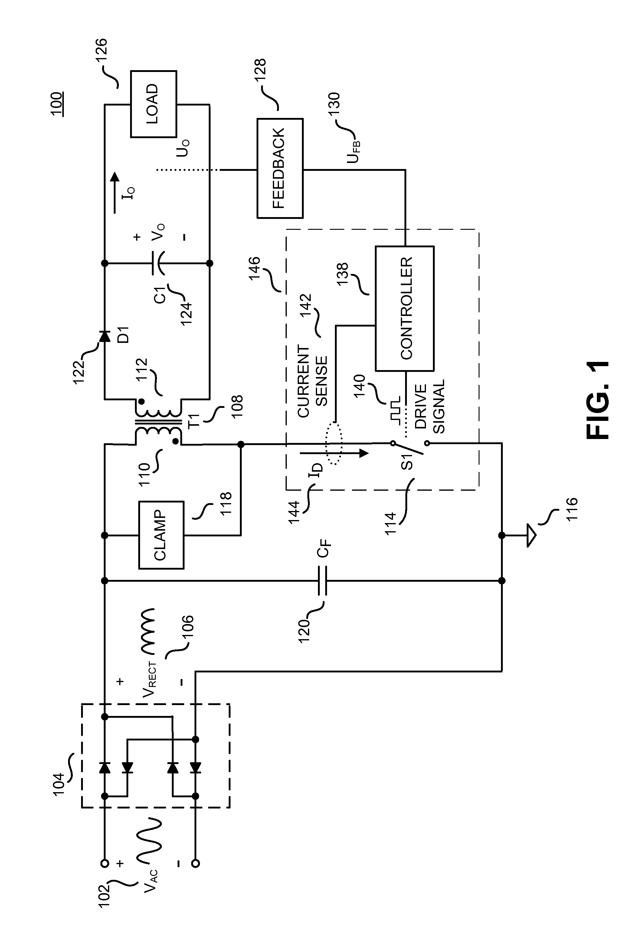
[0028]Embodiments of a method and apparatus for a non-dissipative integrated bleeder for triac dimming of LED drivers for illumination are described herein. In the following description numerous specific details are set forth to provide a thorough understanding of the embodiments. One skilled in the relevant art will recognize, however, that the techniques described herein can be practiced without one or more of the specific details, or with other methods, components, materials, etc. In other instances, well-known structures, materials, or operations are not shown or described in detail to avoid obscuring certain aspects.

[0029]Reference throughout this specification to “one embodiment”, “an embodiment”, “one example” or “an example” means that a particular feature, structure or characteristic described in connection with the embodiment or example is included in at least one embodiment of the present invention. Thus, appearances of the phrases “in one embodiment”, “in an embodiment”,...


PUM


Abstract

An example controller for a switched mode power supply includes a zero-crossing detector, drive logic, and an on-time extension block. The zero-crossing detector is coupled to generate a first signal prior to a zero-crossing of an input voltage of the power supply. The drive logic is to generate a drive logic output signal in response to a feedback signal, where the drive logic output signal is representative of an initial on-time. The on-time extension block is coupled to the zero-crossing detector and to the drive logic to generate a drive signal in response to the drive logic output signal. The drive signal controls switching of a switch to remove charge from a filter capacitor of the power supply. The drive signal is representative of a total on-time of the switch equal to a sum of the initial on-time and an extended on-time, where the extended on-time is responsive to the first signal.

Description

BACKGROUND OF THE INVENTION[0001]1. Field of the Invention[0002]The present invention relates generally to power supplies, and more specifically to controllers for switched mode power supplies.[0003]2. Discussion of the Related Art[0004]Electronic devices use power to operate. Switched mode power supplies are commonly used due to their high efficiency, small size and low weight to power many of today's electronics. Conventional wall sockets provide a high voltage alternating current. In a switching power supply a high voltage alternating current (ac) input is converted to provide a well regulated direct current (dc) output through an energy transfer element. The switched mode power supply control circuit usually provides output regulation by sensing the output and controlling it in a closed loop. In operation, a switch is utilized to provide the desired output by varying the duty cycle (typically the ratio of the on time of the switch to the total switching period) of the switch in ...

Claims


Application Information

Patent Timeline
Patent Type & Authority Applications(United States)
IPC IPC(8): H05B41/36H02M3/335H05B37/02
CPCH02M1/4258H02M5/2573Y02B70/126Y02B20/346H05B33/0815Y02B20/30Y02B70/10H05B45/382
Inventor GAKNOKI, YURYMAO, MINGMINGPASTORE, TIZIANO
Owner POWER INTEGRATIONS INC
Why Eureka
Try Eureka