
Tunable impedance inverter for doherty amplifier circuit

a technology of impedance inverter and amplifier circuit, which is applied in the direction of amplifier types, amplifiers with semiconductor devices/discharge tubes, amplifiers, etc., can solve the problems of conventional doherty amplifiers, linear amplifiers that can provide linear signals at significant cost in efficiency, and amplifiers that suffer from intermodulation and harmonic distortion

Inactive Publication Date: 2011-08-11
HBC SOLUTIONS
View PDF4 Cites 22 Cited by
  • Summary
  • Abstract
  • Description
  • Claims
  • Application Information

AI Technical Summary

Benefits of technology

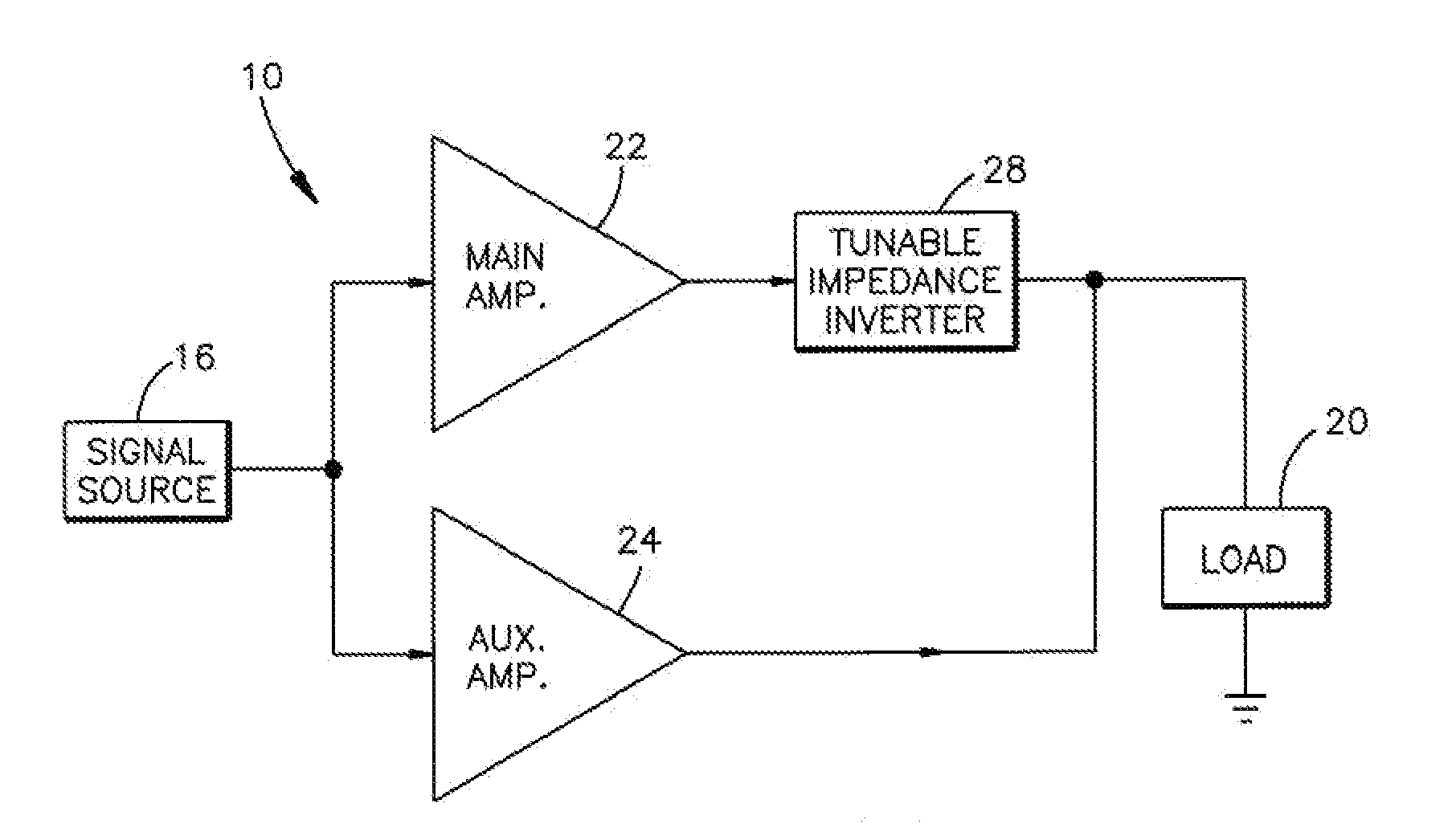
In accordance with one aspect of the present invention, a tunable impedance inverter is presented for a Doherty amplifier circuit having first and second amplifiers connected in parallel between an input circuit for receiving an input signal and an output circuit for supplying an output signal to a load. An impedance inverter is coupled between the first amplifier and the output circuit and a tunable strip line of variable electrical length is interposed between the input and the output of the inverter. An adjuster serves to adjust the electrical length of the strip line. The adjuster adjustably varies the electrical length of the pathway to thereby adjust the center frequency of the output signal.

Problems solved by technology

Linear (Class A) amplifiers can provide a linear signal at a significant cost in efficiency.
More efficient, non-linear (Class C) amplifiers are available, but these amplifiers tend to suffer from intermodulation and harmonic distortion.
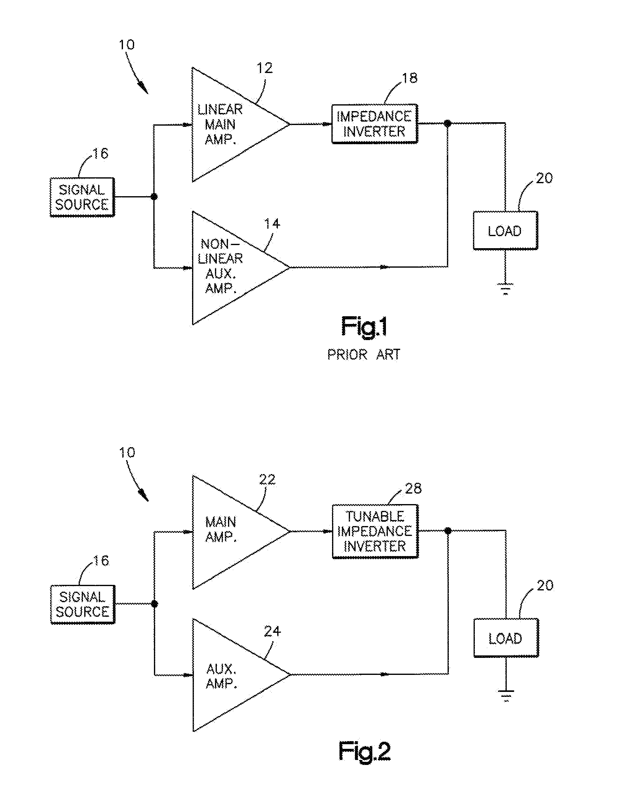
The conventional Doherty amplifier, as presented in FIG. 1, is limited in operation to approximately a 10% bandwidth due to the necessary incorporation of a fixed ¼ wavelength transmission line structure.

Method used


Image

  • Tunable impedance inverter for doherty amplifier circuit
  • Tunable impedance inverter for doherty amplifier circuit
  • Tunable impedance inverter for doherty amplifier circuit

Examples


Embodiment Construction

FIG. 2 is a view similar to that of the prior art in FIG. 1 but illustrating the preferred embodiment of the invention. As shown in FIG. 2, a signal source 16 supplies an input signal to a main amplifier 22 and to an auxiliary amplifier 24 connected together in parallel with a tunable impedance inverter 28 and, hence, to the load 20. In this embodiment, the amplifiers may both be non-linear or the main amplifier may be linear as desired. The tunable impedance inverter differs substantially from the inverter 18 which is a fixed quarter wavelength strip line. The inverter 28 is tunable over a wide frequency band such as from 330 MHz to 1 GHz.

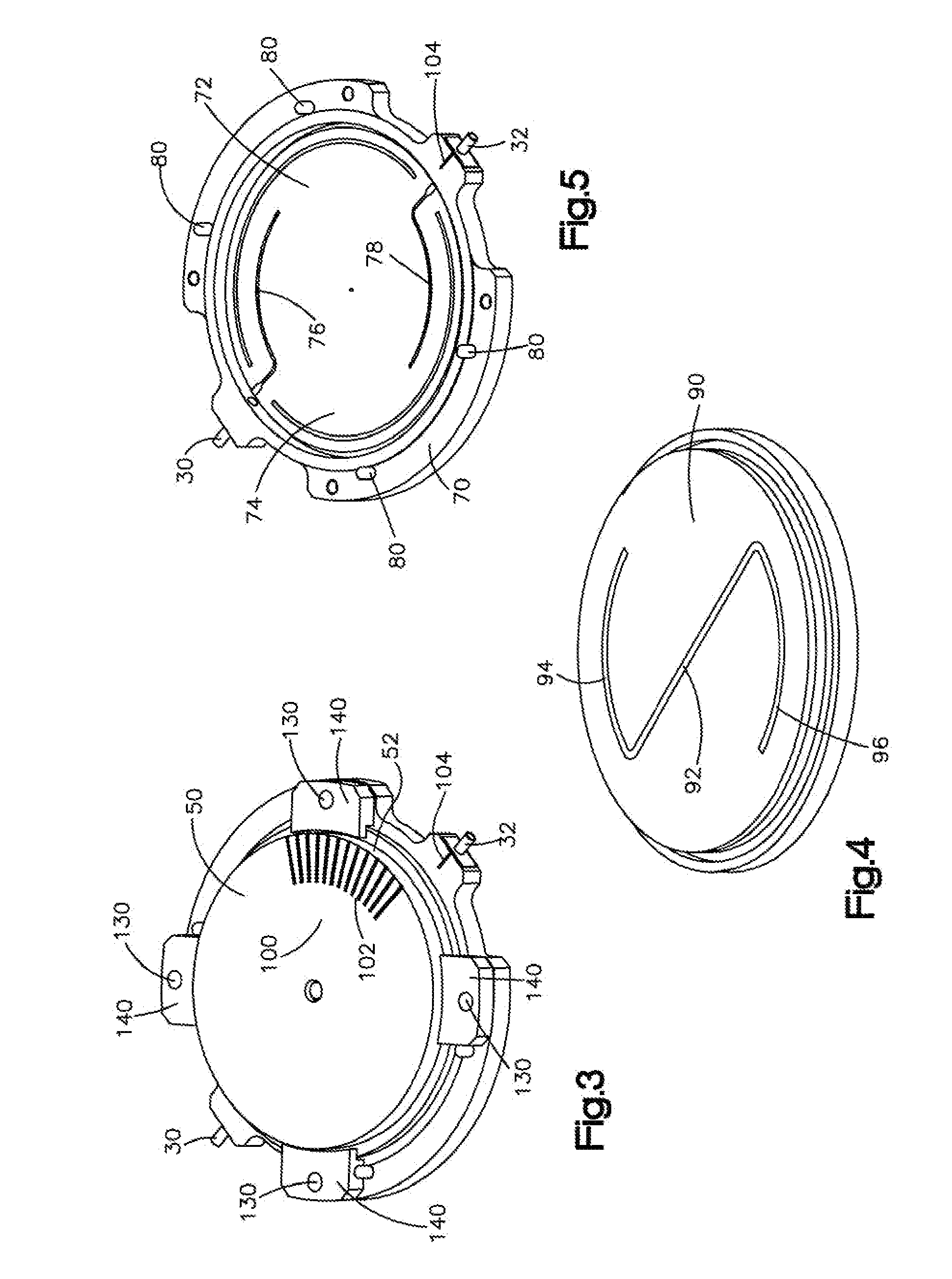
As shown in FIG. 3-8, the inverter 28 is a multi-layered disc-shaped device which, as will be seen, provides a variable electrical length pathway between the input port 30 and the output port 32 when the upper assembly is rotated about the Z axis (see FIG. 6) either in a clockwise direction or in a counterclockwise direction. The top assembly, as ...


PUM


Abstract

A tunable impedance inverter is presented for a Doherty amplifier circuit having first and second amplifiers connected in parallel between an input circuit for receiving an input signal and an output circuit for supplying an output signal to a load. An impedance inverter is coupled between the first amplifier and the output circuit. The inverter has an input and an output and a tunable mechanical strip line of variable electrical length interposed between the input and the output. An adjuster adjusts the electrical length of the strip line. The adjuster adjustably varies the electrical length of said pathway to thereby adjust the center frequency of said output signal.

Description

TECHNICAL FIELDThe present invention relates to RF communication systems and is particularly directed to a modified Doherty amplifier having a tunable impedance inverter.BACKGROUND OF THE INVENTIONTelevision broadcast systems in the ultrahigh-frequency (UHF) region from 470 to 860 MHz are transitioning from analog to digital technology, and broadcasters are taking advantage of digital performance while attempting to keep equipment costs low. Since one of the highest cost components is the transmitter, this is an area where improvements may result in reduced overall costs.Most digital vector modulation schemes require linear amplification. For many systems, this is achieved using solid state devices. High power tubes are still used for power applications in the kilowatt range, transitioning to a lower cost high frequency solid state transmitter design with enough bandwidth for broadcasting will be needed.In many of the broadcast applications, the amplifier design may result in a bala...

Claims


Application Information

Patent Timeline
Patent Type & Authority Applications(United States)
IPC IPC(8): H03F3/68
CPCH01P5/04H03F1/0288H03F1/56H03F2200/543H03F2200/387H03F2200/423H03F2200/451H03F3/602
Inventor SCOTT, WILLIAM GARYSANTO-TOMAS, RAMON A.CABRERA, GEORGEHASH, RONALD J.
Owner HBC SOLUTIONS
Learn More