
Liquid Crystal Display and Pulse Adjustment Circuit Thereof

a technology of pulse adjustment and liquid crystal display, which is applied in the direction of electric digital data processing, instruments, computing, etc., can solve the problems of uneven brightness of all the colors in the subpixels and affect display performance, and achieve the effect of improving the picture display quality of the lcd apparatus

Active Publication Date: 2011-08-11
AU OPTRONICS CORP
View PDF42 Cites 9 Cited by
  • Summary
  • Abstract
  • Description
  • Claims
  • Application Information

AI Technical Summary

Benefits of technology

"The present invention provides a pulse adjustment circuit that can change the driving waveform inputted into a driving circuit, reducing the feedthrough voltage difference between adjacent subpixels and improving the picture display quality of a liquid crystal display (LCD) apparatus. The pulse adjustment circuit comprises a first switch and a discharge unit that determine the timing of power signal transmission to the gate driver, and a signal generator and a selector that determine the timing of power signal transmission to the gate driver in response to a set of control signals. The power signals transmitted to the gate driver determine the amplitude of the input pulse signal, with at least one of the amplitudes being larger than another. The technical effects of the invention include reducing the feedthrough voltage difference between adjacent subpixels, improving the picture display quality of the LCD apparatus, and adjusting the power signal provided from the power supply to the gate drivers."

Problems solved by technology

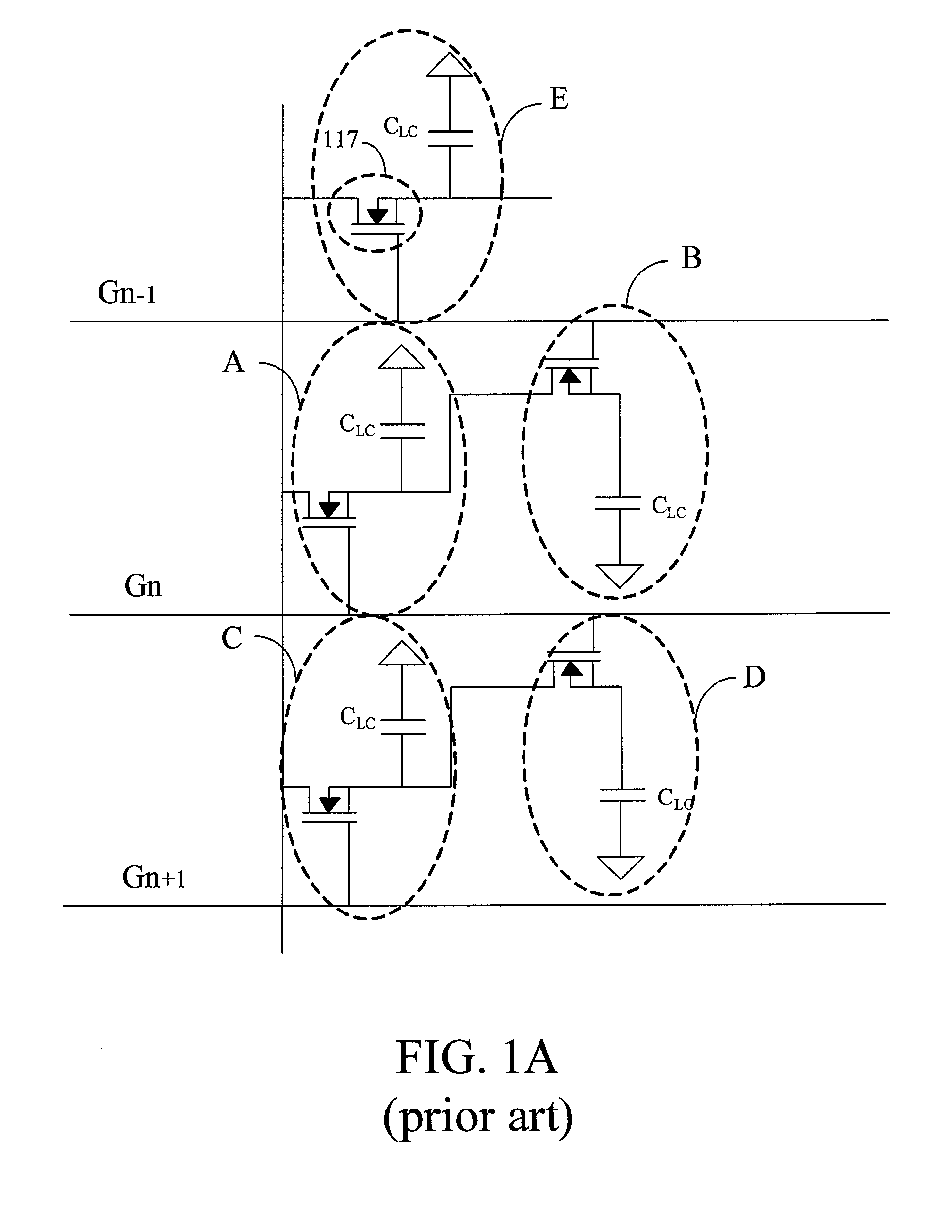
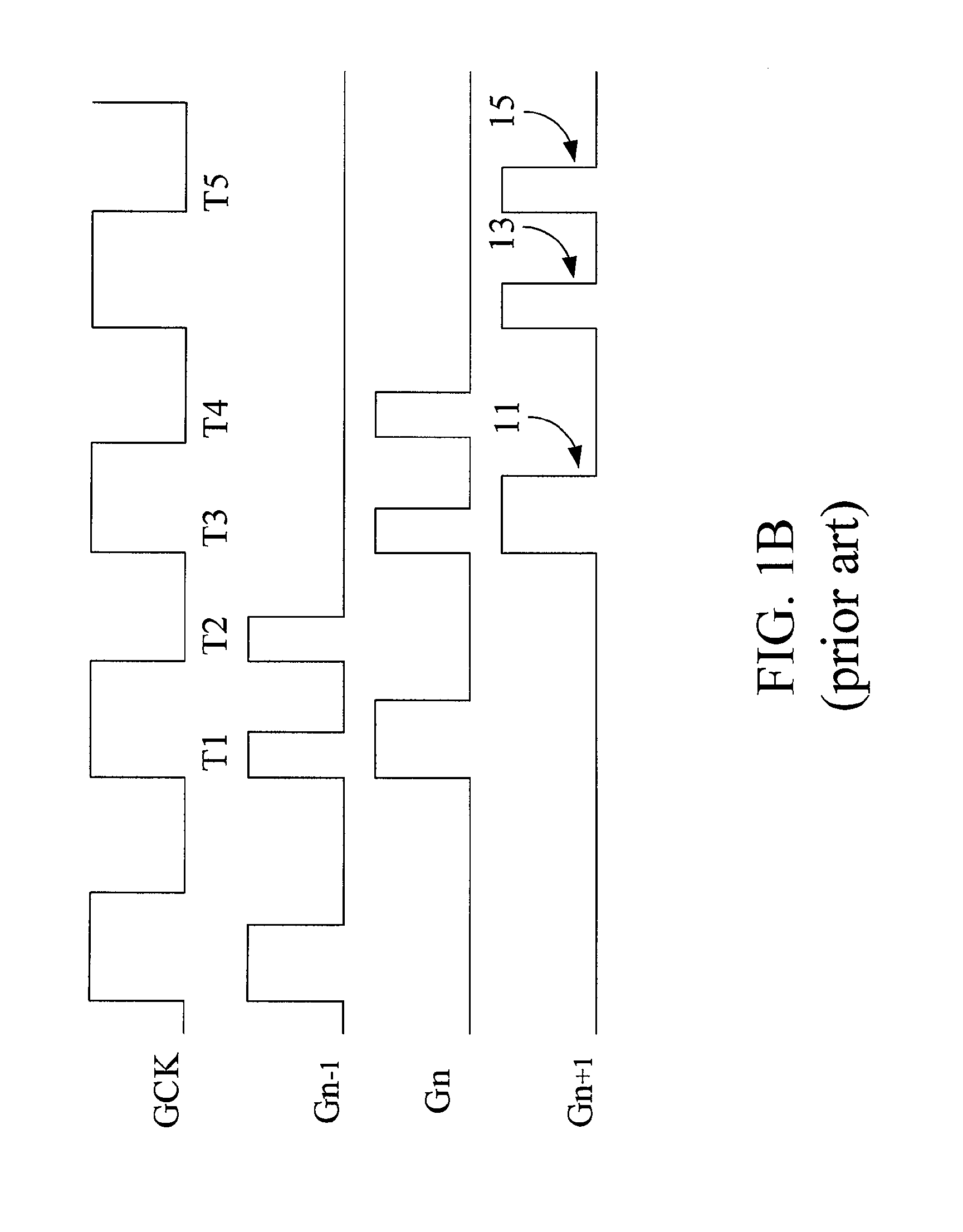
In the end, the final voltages of the two adjacent subpixels are different, the charged data voltages in the subpixels are different, and thus, the brightness of all the colors in the subpixels is uneven enough that the display performance is affected.

Method used


Image

  • Liquid Crystal Display and Pulse Adjustment Circuit Thereof
  • Liquid Crystal Display and Pulse Adjustment Circuit Thereof
  • Liquid Crystal Display and Pulse Adjustment Circuit Thereof

Examples


first embodiment

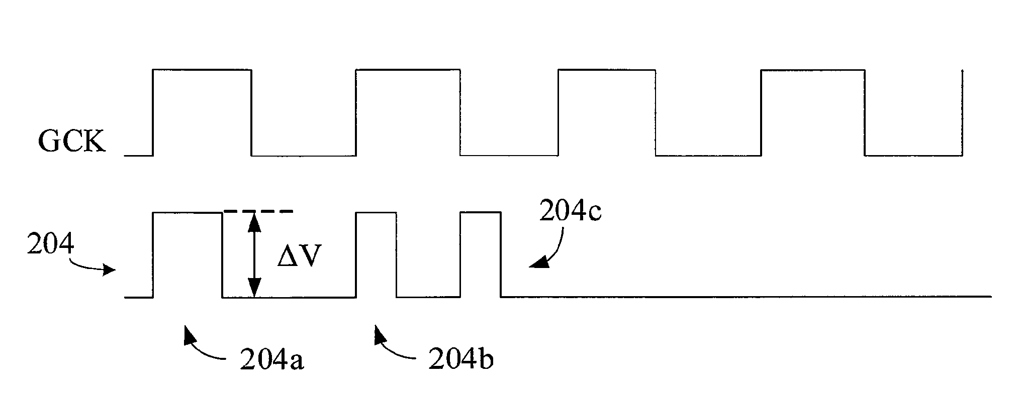
[0036]the present invention is an LCD apparatus 2, especially a TFT LCD, as shown in FIG. 2. The LCD apparatus 2 comprises a power supply 20, a plurality of pulse adjustment circuits 21, a plurality of gate drivers 22, a plurality of source drivers 23, and an LCD panel 24. The LCD apparatus 2 incorporates the MSHD technology and comprises fewer source drivers.

[0037]The details of the structural connections of the power supply 20, one pulse adjustment circuit, and one gate driver 22 are shown in FIG. 2A. The pulse adjustment circuit 21 is connected between the power supply 20 and the gate driver 22. Another end of the gate driver 22 is connected to one scan line of the active matrix driving circuit. The power supply 20 provides a power signal 202. The power signal 202 can be a direct current (DC) voltage signal in this embodiment. The pulse adjustment circuit 21 comprises a first switch 211 and a discharge unit 213. The discharge unit 213 comprises a resistance 215 and a second switc...

second embodiment

[0044]the present invention is also an LCD apparatus 2 as shown in FIG. 2. The details of the structural connection of the power supply 20, a pulse adjustment circuit, and a gate driver 22 are shown in FIG. 3A. The pulse adjustment circuit 21 is connected between the power supply 20 and the gate driver 22. Another end of the gate driver 22 is connected to one scan line of the active matrix driving circuit. The power supply 20 provides a plurality of power signals 302. These power signals 302 have different voltage levels. The first positive level voltage signal V1, second positive level voltage signal V2, and negative level voltage signal V3, wherein V1 is 25 volts, V2 is 18 volts, and V3 is −6 volts.

[0045]The pulse adjustment circuit 21 comprises a signal generator 311 and a selector 313. The signal generator 311 generates a set of control signals SC1 and SC2. The selector 313 determines a timing of transmitting which of the power signals 302 to the gate driver in response to the s...

third embodiment

[0048]the present invention is also the LCD apparatus 2 as shown in FIG. 2. The details of the structural connection of the power supply 20, a pulse adjustment circuit, and a gate driver 22 are shown in FIG. 4A. The power supply 20 provides three kinds of direct current voltage signals, which are a second positive level voltage signal V2, a first negative level voltage signal V3, and a second negative level voltage signal V4, wherein V2 is 18 volts, V3 is −6 volts, and V4 is −10 volts.

[0049]The pulse adjustment circuit 21 also comprises a signal generator 411 and a selector 413. The signal generator 411 generates a set of control signals SC1 and SC2. The selector 413 determines a timing to transmit which of the power signals 302 to the gate driver 22 in response to the set of control signals. The control signal SC1 is configured to determine the timing of transmitting the positive level voltage signal V2 of the determined power signals 402 to the gate driver 22, while the control si...


PUM


Abstract

A liquid crystal display comprises a power supply, a pulse adjustment circuit, and a gate driver. The pulse adjustment circuit is connected between the power supply and the gate driver. The power supply provides power signals. The pulse adjustment circuit adjusts the plurality of pulses of the power signals or selects the appropriate voltage levels for the power signals to have cutting angles or enlarged amplitudes, whereby the influence of the feedthrough voltage on the thin film transistors of the driving circuit would be reduced so that the display quality of the liquid crystal display is improved.

Description

CROSS-REFERENCES TO RELATED APPLICATIONS[0001]This application is a divisional of U.S. application Ser. No. 11 / 971,627, filed Jan. 9, 2008, which claims the benefit from the priority of Taiwan Patent Application No. 096108866 filed on Mar. 15, 2007, the disclosures of which are incorporated by reference herein in their entirety.BACKGROUND OF THE INVENTION[0002]1. Field of the Invention[0003]The present invention relates to a liquid crystal display (LCD) and a pulse adjustment circuit thereof.[0004]2. Descriptions of the Related Art[0005]With the rapid development of consumer electronic technology, people are becoming accustomed to using various electronic products, such as electronic multimedia products. One key component of multimedia electronic products is the display. Since liquid crystal displays (LCDs) have properties such as radiation-free, low power consumption, a plane square shape, high resolution, and stable display quality, LCDs have gradually replaced the traditional cat...

Claims


Application Information

Patent Timeline
Patent Type & Authority Applications(United States)
IPC IPC(8): G09G3/36G09G5/00
CPCG09G3/3648G09G3/3677G09G2320/0219G09G2310/06G09G3/3696
Inventor HSU, WEN FAHUNG, CHI MAO
Owner AU OPTRONICS CORP
Learn More