Imaging device, imaging device control method and program

a technology of imaging device and control method, which is applied in the direction of exposure control, camera filters, instruments, etc., can solve the problems of unstable operation of imaging device, deterioration of signal-to-noise and deterioration of s/n ratio of image obtained by image capture. to achieve the effect of improving the s/n ratio of imag

Inactive Publication Date: 2011-08-11
SONY CORP
View PDF4 Cites 91 Cited by
  • Summary
  • Abstract
  • Description
  • Claims
  • Application Information

AI Technical Summary

Benefits of technology

[0019]According to the present invention described above, it is possible to remove the infrared cut filter from the opti

Problems solved by technology

As a result, when the image capture environment becomes dark, a signal-to-noise (S/N) ratio of the image obtained by image capture deteriorates.
However, in the control of the gain and the infrared irradiation intensity in the night mode, if an image is ca

Method used


Image

  • Imaging device, imaging device control method and program
  • Imaging device, imaging device control method and program
  • Imaging device, imaging device control method and program

Examples


Embodiment Construction

[0030]Hereinafter, preferred embodiments of the present invention will be described in detail with reference to the appended drawings. Note that, in this specification and the appended drawings, structural elements that have substantially the same function and structure are denoted with the same reference numerals, and repeated explanation of these structural elements is omitted.

[0031]Note that the description will be made in the following order.[0032]1. Configuration of embodiment[0033]2. Operations of embodiment[0034]3. Advantageous effects of embodiment

1. Configuration of Embodiment

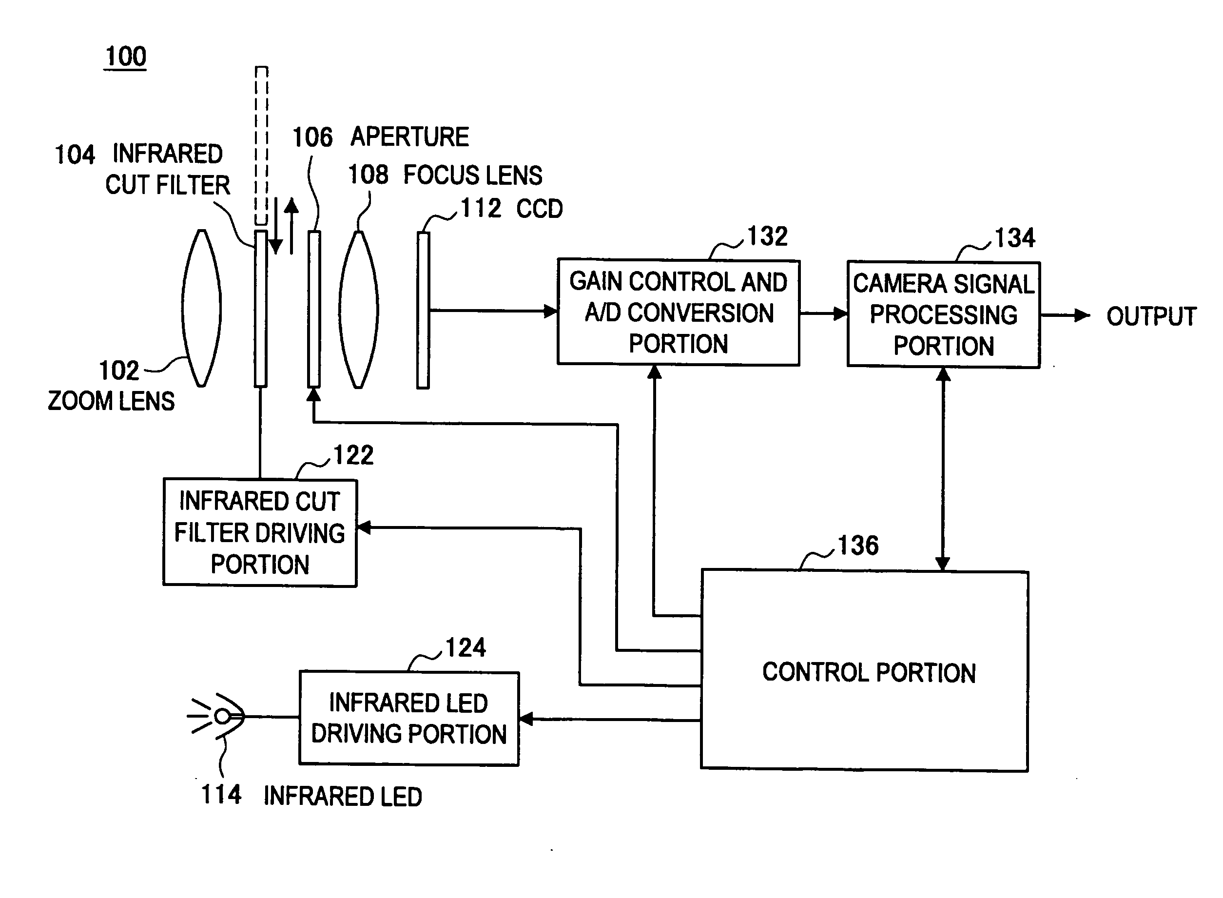
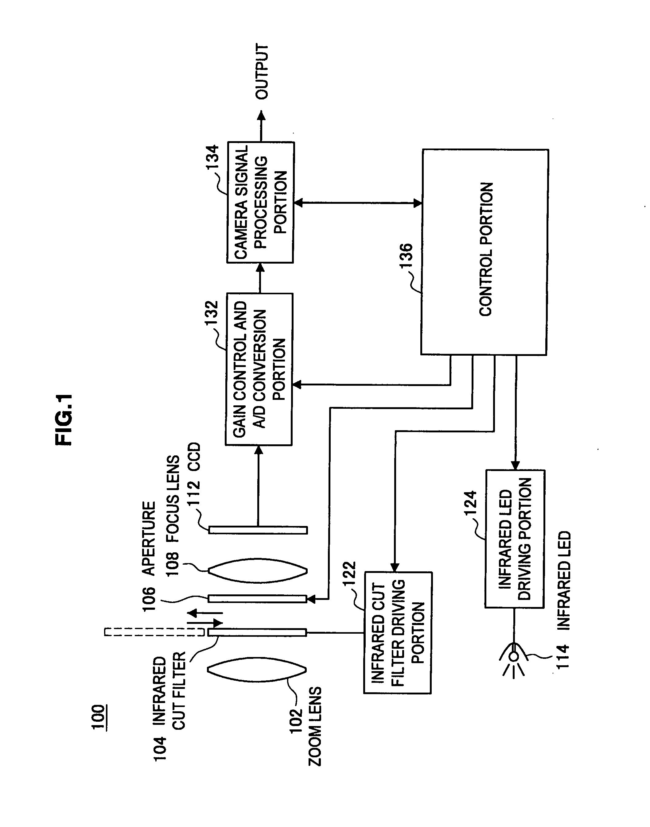
[0035]First, a configuration of an imaging device 100 according to an embodiment of the present invention will be explained with reference to FIG. 1. FIG. 1 is a block diagram showing the imaging device 100 according to the present embodiment.

[0036]The imaging device 100 is, for example, a video camera or the like that captures moving images. The imaging device 100 captures a subject in two modes, i.e....


PUM


Abstract

An imaging device that includes a control unit is provided. The control unit switches between a day mode and a night mode. In the day mode, image capture is performed while an infrared cut filter is placed on an optical path, and in the night mode, image capture is performed while the infrared cut filter is removed from the optical path. Immediately after shifting from the day mode to the night mode, in the night mode, as the amount of incident light decreases, the control unit increases an irradiation intensity of an infrared irradiation portion from zero while a gain is maintained at a first gain value. When the amount of the incident light further decreases after the irradiation intensity reaches a maximum, the control portion increases the gain from the first gain value.

Description

CROSS-REFERENCE TO RELATED APPLICATION[0001]The present application claims priority from Japanese Patent Application No. JP 2010-028041 filed in the Japanese Patent Office on Feb. 10, 2010, the entire content of which is incorporated herein by reference.BACKGROUND OF THE INVENTION[0002]1. Field of the Invention[0003]The present invention relates to an imaging device, an imaging device control method and a program.[0004]2. Description of the Related Art[0005]Imaging devices (such as a video camera, a digital still camera and the like) that can capture infrared light are known. When an imaging device that can capture infrared light is used for image capture, during daylight hours when the image capture environment is bright, an infrared cut filter is attached to a stage preceding a charge coupled device (CCD) image sensor and image capture is performed. On the other hand, during night hours when the image capture environment is dark, the infrared cut filter is removed from an optical ...

Claims


Application Information

Patent Timeline
IPC IPC(8): H04N5/33G03B7/18G03B11/00G03B17/00G03B17/02H04N5/238H04N101/00
CPCG03B7/18H04N5/2352H04N5/23245H04N5/2254H04N23/60H04N23/667H04N23/72
Inventor MATSUMOTO, TAKUYAZHOU, XIAOBOPAN, YUANYUANLI, LI
Owner SONY CORP
Why Eureka
Try Eureka