

Clock generator, pulse generator utilizing the clock generator, and methods thereof
- Summary
- Abstract
- Description
- Claims
- Application Information
AI Technical Summary
Benefits of technology
Problems solved by technology
Method used
Image

Examples
first embodiment
[0032]FIG. 3a is a schematic diagram illustrating a clock generator 300 according to the present invention. The clock generator 300 may include: a control circuit 303, a clock gating circuit 305 and a delay module 307. A reference clock generator 301 may also be included in the clock generator 300. It is not necessary to have the reference clock generator, though the reference clock generators are included in the embodiments illustrated herein. The reference clock could be generated by any other components inside or outside the clock generator and pulse generator according to this invention. The reference clock generator 301 serves to generate a reference clock signal RCLK. The control circuit 303 receives the reference clock signal RCLK, and generates a clock enable signal EN and a delay selecting signal DS according to the reference clock signal RCLK. The clock gating unit 305 receives the reference clock RCLK and the clock enable signal EN, and passes the reference clock signal R...
second embodiment
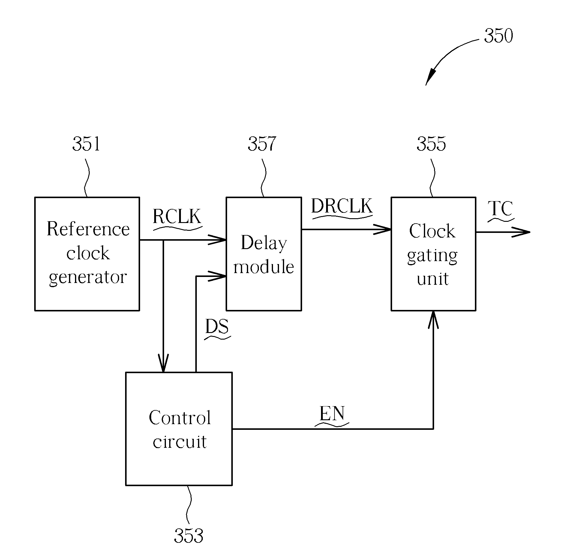
[0034]FIG. 3c is a schematic diagram illustrating a clock generator 350 according to the present invention. Compared with the embodiment shown in FIG. 3a, the clock generator 350 also includes a control circuit 353, a clock gating circuit 355 and a delay module 357. A reference clock generator 351 may also be included. However, the clock gating circuit 355 is a following stage of the delay module 357 instead of a front stage of the delay module 357. Therefore, the embodiments shown in FIGS. 3a and 3c have some different operations. In the embodiment shown in FIG. 3c, the delay module 357 receives the reference clock RCLK and the delay selecting signal DS, and delays the reference clock RCLK according to the delay selecting signal DS. Then, the clock gating unit 355 receives the delayed reference clock DRCLK and the clock enable signal EN, and passes the delayed reference clock signal DRCLK according to the clock enable signal EN, to generate the target clock signal TC.
third embodiment
[0035]FIG. 4 is a block diagram illustrating a delay module 401 according to the present invention which can solve the skew problem illustrated in FIG. 2. As shown in FIG. 4, the delay module 401 can include a plurality of delay blocks 403, 405, which can include delay units 407, 411, respectively, and selectors 409, 413. Additionally, the delay module 401 can further include a register 415, which is a D flip flop in the embodiment shown in FIG. 4. However, other components capable of registering, such as a latch, may also act as the register 415. The delay selecting signal DS2 is registered by the register 415 and outputted as a registered delay selecting signal RDS according to the first output signal Fout, which is generated by processing the input signal IN via the delay block 403. Next, the delay block 405 processes the first output signal Fout to generate an output signal DSout according to the registered delay selecting signal RDS. It should be noted that the delay selecting ...
PUM
 Abstract
Description
Claims
Application Information