
X-ray CT apparatus and method thereof

a technology of x-ray ct and x-ray ct, which is applied in the field of x-ray ct apparatus and an x-ray ct method, can solve the problems of subject exposure and reduce the effect of contrast medium

Active Publication Date: 2011-08-11
MITSUBISHI CHEM CORP
View PDF7 Cites 8 Cited by
  • Summary
  • Abstract
  • Description
  • Claims
  • Application Information

AI Technical Summary

Benefits of technology

"The present invention provides an X-ray CT apparatus and method that can generate stable and independent X-ray CT images regardless of the size of the subject and X-ray tube voltage. The apparatus calculates the thickness of the object being inspected by analyzing the number of transmitted X-rays in specific energy ranges. This allows for a more accurate and reliable method of reconstructing a CT image."

Problems solved by technology

This gives rise to the problem of subject exposure.
This reduces the effect of the contrast medium.

Method used


Image

  • X-ray CT apparatus and method thereof
  • X-ray CT apparatus and method thereof
  • X-ray CT apparatus and method thereof

Examples


embodiment operation

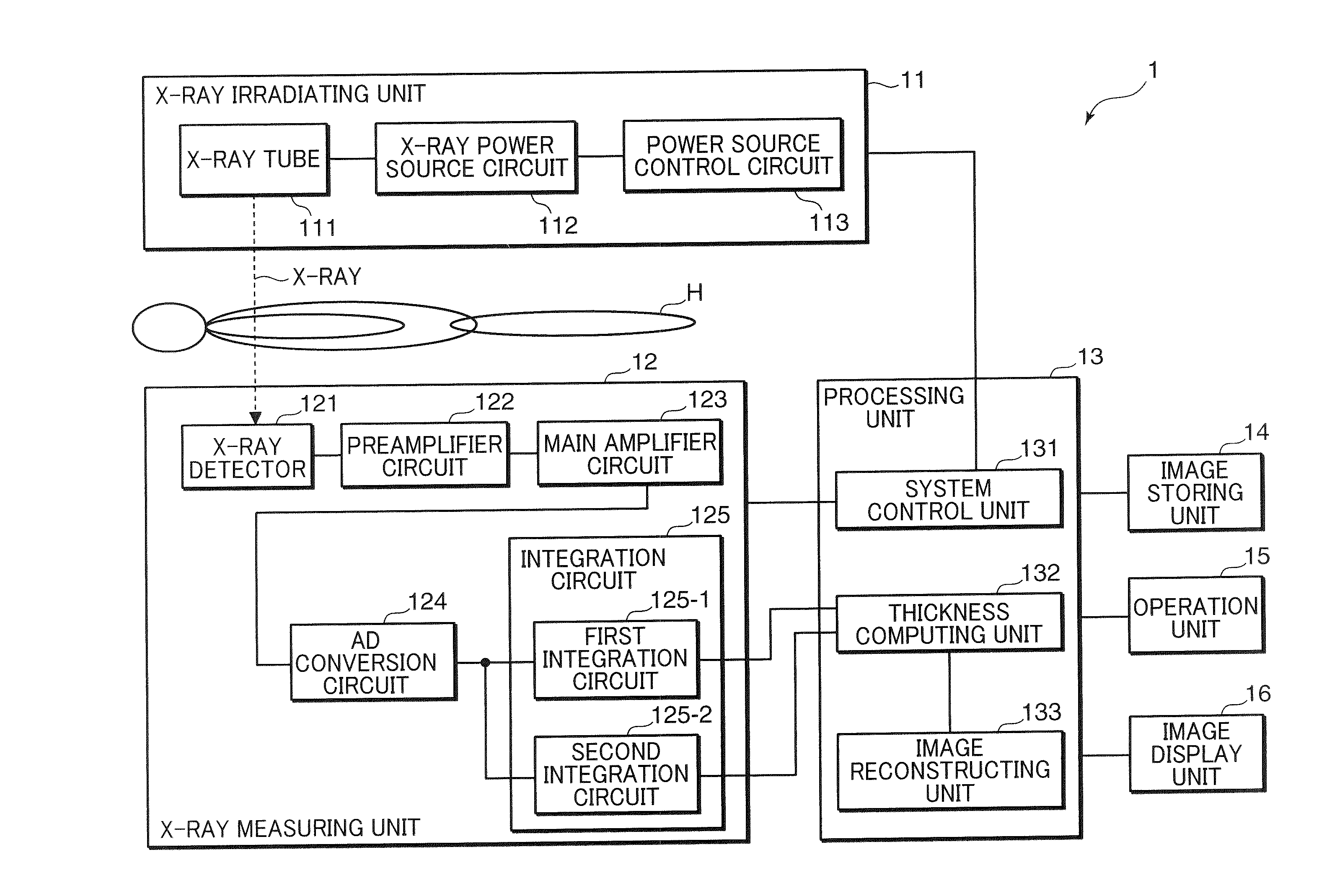
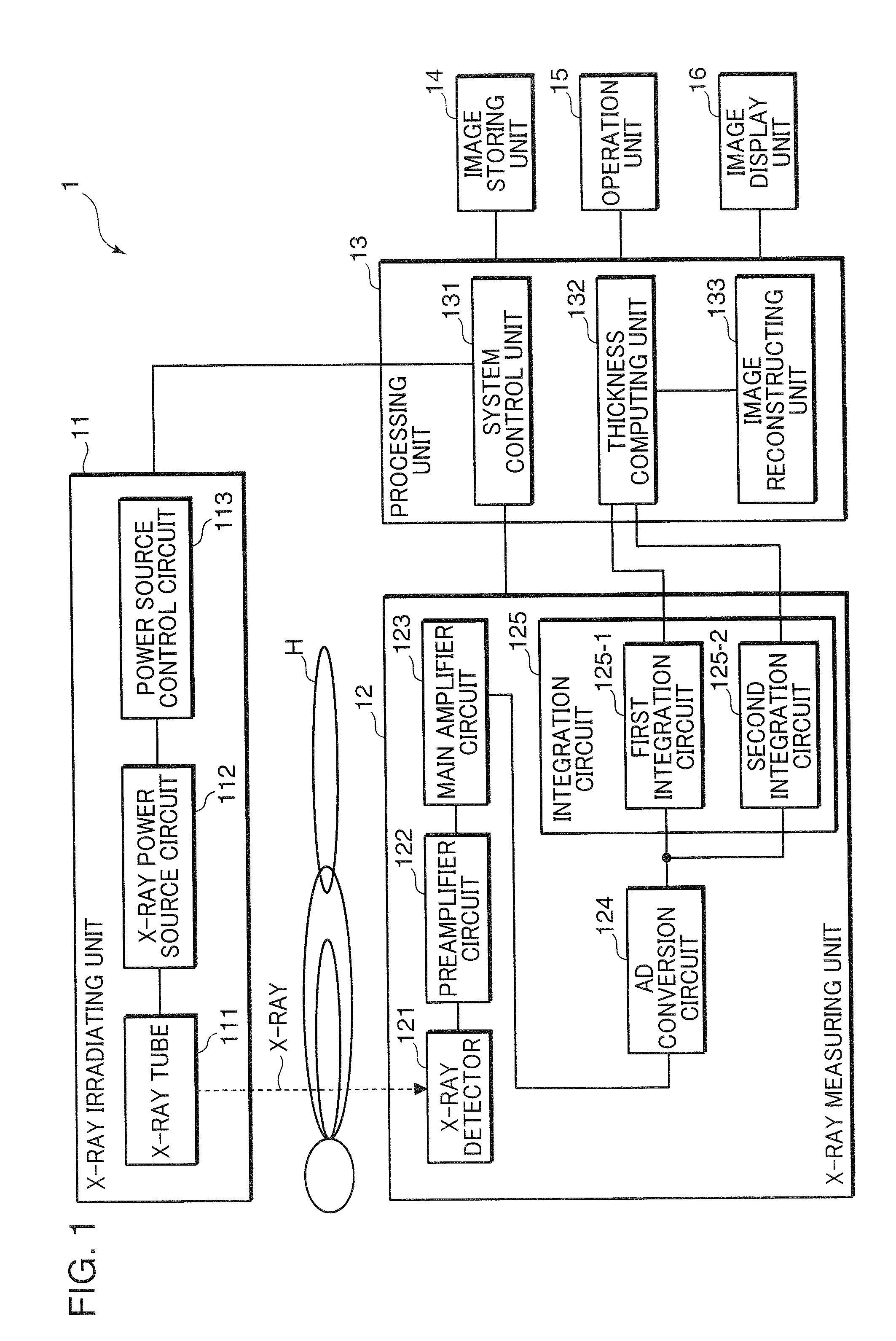
[0043]An appropriate contrast medium is selected from among X-ray contrast media such as an iodine contrast medium, a barium contrast medium or a gold contrast medium, in accordance with the diagnosis target and diagnosis site, and is administered to the subject H. The user inputs then an imaging start instruction by way of the operation unit 15, whereupon the X-ray irradiating unit 11 is controlled by the system control unit 131 of the processing unit 13 to cause the X-ray irradiating unit 11 to irradiate X-rays onto the subject H. The X-ray measuring unit 12 is controlled so that transmitted X-rays that pass through the subject H are measured by the X-ray measuring unit 12. Specifically, upon receiving a control signal from the processing unit 13, the power source control circuit 113 of the X-ray irradiating unit 11 controls the X-ray power source circuit 112 to cause thereby a power of a predetermined voltage to be supplied, at a predetermined timing, to the X-ray tube 111 from t...


PUM


Abstract

In an X-ray CT apparatus 1 and an X-ray CT method, the thickness of an object to be inspected is computed on the basis of the number of transmitted X-rays in a specific energy range set above and below the K-absorption edge of an X-ray contrast medium serving as the object to be inspected, and a CT image is reconstructed on the basis of the computed thickness of the object to be inspected. Such X-ray CT apparatus 1 and X-ray CT method can generate an X-ray CT image stably and independently of the size of the object to be inspected and of X-ray tube voltage (X-ray energy distribution).

Description

TECHNICAL FIELD[0001]The present invention relates to an X-ray CT apparatus and an X-ray CT method, and more particularly to an X-ray CT apparatus and an X-ray CT method for generating a CT image based on energy information of transmitted X-rays.BACKGROUND ART[0002]Diagnostic imaging based on X-ray transmission imaging or X-ray CT (computed tomography) imaging enables the finding of pathologies such as tumors, ulcers and the like inside a subject, and is therefore used as an effective diagnostic method. In such diagnostic imaging, there is measured the dose of X-rays that pass through a subject (or the dose of X-rays absorbed by a subject). An X-ray image is then generated by graphically representing the measured changes in X-ray dose. The elements present in a living organism are relatively light elements such as hydrogen, nitrogen, oxygen and calcium. The X-ray absorption coefficient of such elements is therefore small. In consequence, the X-ray dose irradiated to the subject must...

Claims


Application Information

Patent Timeline
Patent Type & Authority Applications(United States)
IPC IPC(8): A61B6/03
CPCA61B6/032A61B6/4035A61B6/4042A61B6/405A61B6/583A61B6/481A61B6/482A61B6/504A61B6/544A61B6/4241G01N23/087G01N23/046
Inventor KANNO, IKUO
Owner MITSUBISHI CHEM CORP
Learn More