
Device and method for storage tank restraint on a vehicle

a technology for a storage tank and a device, which is applied in the direction of washstands, lightening support devices, scaffold accessories, etc., can solve the problems of difficult access to the securing bolts, no speedy and simple removal and replacement of empty ammonia tanks, and high concentration of no/sub>x, etc., to achieve the effect of adding structural and operating advantages

Inactive Publication Date: 2011-08-18
INT ENGINE INTPROP CO LLC
View PDF3 Cites 11 Cited by
  • Summary
  • Abstract
  • Description
  • Claims
  • Application Information

AI Technical Summary

Benefits of technology

[0006]There is disclosed herein a device, system and method, each of which avoids the disadvantages of prior devices, systems and methods while affording additional structural and operating advantages.
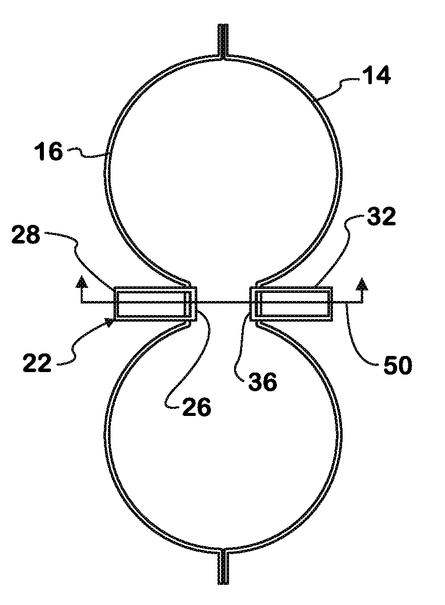
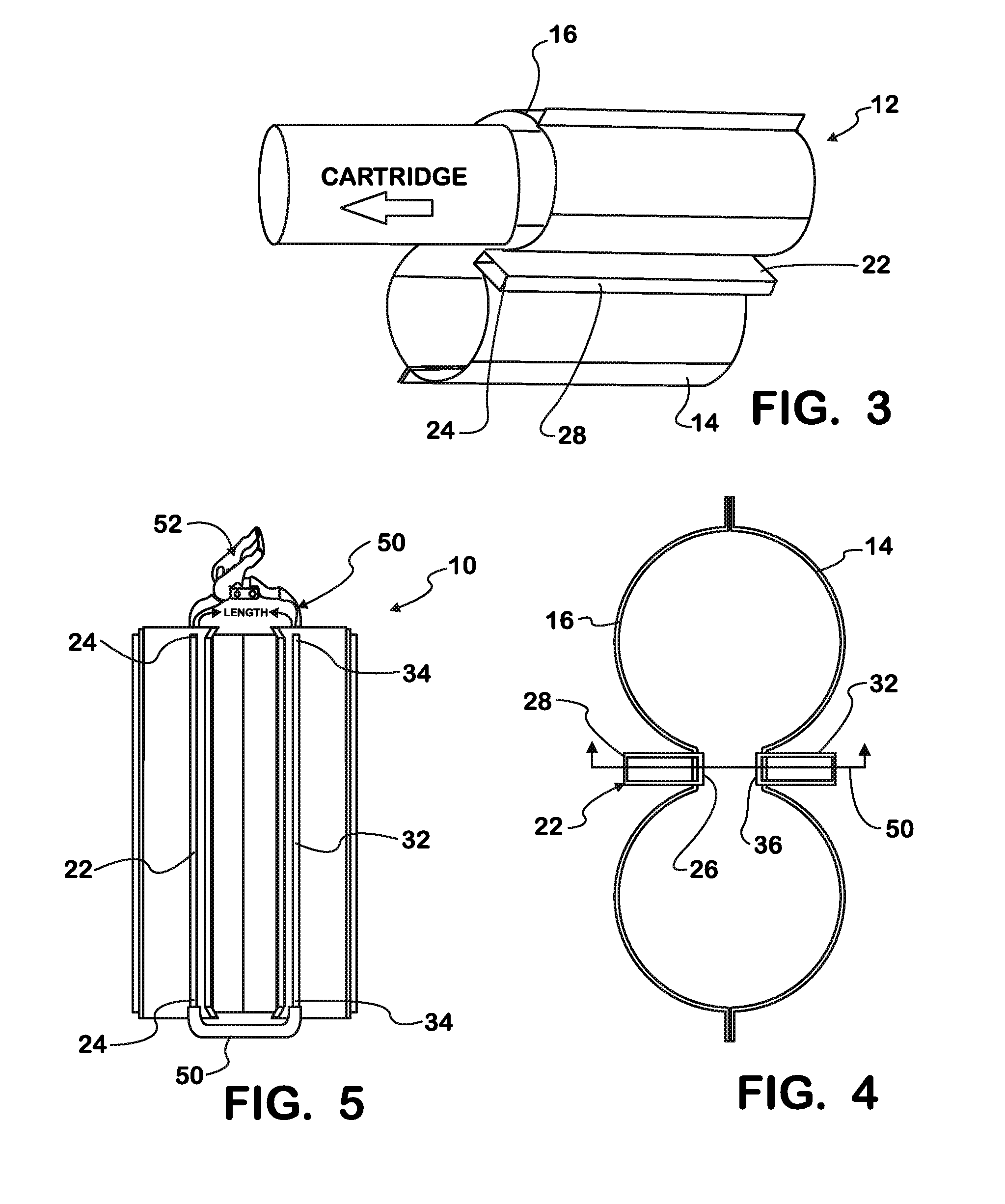
[0012]The first support of the embodiment is fixedly attached to the frame of the vehicle and contacts the first complementary portion of the cartridge holder, while the second support is positioned across the second complementary portion of the cartridge holder opposite and parallel to the first support. The connecting support attaches to the first and second supports to form an open loop about the first and second complementary portions of the heating mantle, and the release allows the second support to move away from the cartridge holder to permit access to the interior space.

Problems solved by technology

New and existing regulations continually challenge manufacturers to achieve good fuel economy and reduce the particulates and NOx emissions.
Lean-burn engines achieve the fuel economy objective, but the high concentrations of oxygen in the exhaust of these engines yields significantly high concentrations of NOx as well.
A drawback of the standard holder structure is that removing and replacing empty ammonia tanks is neither speedy nor simple due to the sometimes limited space for placement of the holder making access to the securing bolts very difficult.

Method used


Image

  • Device and method for storage tank restraint on a vehicle
  • Device and method for storage tank restraint on a vehicle
  • Device and method for storage tank restraint on a vehicle

Examples


Embodiment Construction

[0023]While this invention is susceptible of embodiments in many different forms, there is shown in the drawings and will herein be described in detail a preferred embodiment of the invention with the understanding that the present disclosure is to be considered as an exemplification of the principles of the invention and is not intended to limit the broad aspect of the invention to embodiments illustrated.

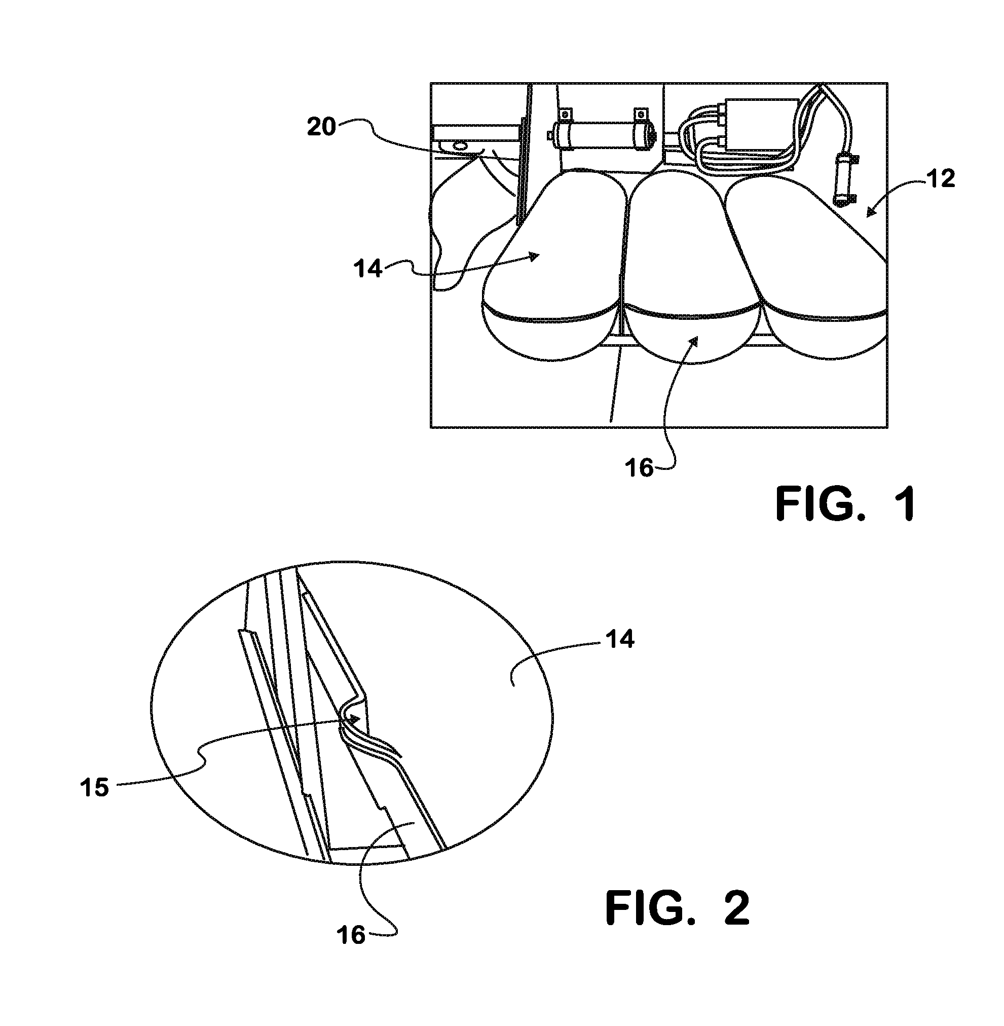
[0024]Referring to FIGS. 1-7, there is illustrated a restraint method and device for restraining a storage tank holder onto a vehicle frame. The restraint device of the present invention, generally designated by the numeral 10, is discussed with respect to a holder for ammonia storage tanks or cartridges, such as those used to supply ammonia gas to a combustion engine as a fuel-containing mixture. However, the particular holder may be used for retaining any type of suitable replaceable storage tank, including water tanks, air tanks, and the like.

[0025]FIGS. 1-3, illustrate current...


PUM

PropertyMeasurementUnit
perimeteraaaaaaaaaa
lengthaaaaaaaaaa
flexibleaaaaaaaaaa

Abstract

A restraint device and method for securing an ammonia storage tank holder to a frame is disclosed. The restraint device includes first and second supports which sandwich about the holder in a parallel fashion. A connecting support attaches to and holds the first and second supports in a substantially parallel relationship about the storage tank holder, and is adjustable such that the second support is selectively movable to expand the perimeter of the holding space. The disclosed method includes the steps of affixing a first support having first and second ends to a frame of a vehicle, placing a storage tank holder into contact with at least one surface of the first support, placing a second support having first and second ends substantially parallel to the first support in contact with a surface of the storage tank holder opposite the first support, and securing the first and second supports.

Description

TECHNICAL FIELD OF THE INVENTION[0001]The present device and method relate to a restraint device for a storage tank holder. Particularly, the device relates to a restraint device for securing a storage tank holder onto a vehicle frame.BACKGROUND OF THE INVENTION[0002]Compression ignition engines provide advantages in fuel economy, but produce both NOx and particulates during normal operation. New and existing regulations continually challenge manufacturers to achieve good fuel economy and reduce the particulates and NOx emissions. Lean-burn engines achieve the fuel economy objective, but the high concentrations of oxygen in the exhaust of these engines yields significantly high concentrations of NOx as well. Accordingly, the use of NOx reducing exhaust treatment schemes are being employed in a growing number of systems.[0003]One such system is the direct addition of ammonia gas to the exhaust stream. However, the ammonia addition method for controlling NOx requires onboard retention...

Claims


Application Information

Patent Timeline
Patent Type & Authority Applications(United States)
IPC IPC(8): F16M13/02B23P11/00
CPCF01N3/2066F01N13/1822F01N2450/18F01N2450/30Y10T29/4984F01N2610/10F01N2610/1406Y10T29/49826F01N2610/02Y02A50/20
Inventor GRIFFIN, GREGORY A.YOON, TIMOTHY
Owner INT ENGINE INTPROP CO LLC
Learn More