Optimized Scoop for Improved Gob Shape

a technology of optimizing which is applied in the field of optimizing the scoop for can solve problems such as glass container defects, and achieve the effects of improving the centripetal force, and improving the shape of the gob

Inactive Publication Date: 2011-08-18
EMHART GLASS SA
View PDF19 Cites 3 Cited by
  • Summary
  • Abstract
  • Description
  • Claims
  • Application Information

AI Technical Summary

Benefits of technology

[0053]As the glass gob goes around the curvature of the optimized scoop 50, the centripetal force increases, which leads to elongation of the glass gob. (This is why glass gob elongation is only seen on scoops and deflectors, not on troughs, since it is the centripetal force on the glass gob that causes it to elongate.) By applying this normal force analysis approach, a trajectory profile chosen based upon a computational fluid dynamics result may be verified. An optimum trajectory for the optimized scoop 50 will have a smooth increase in the centripetal force, while reducing the maximum normal force to which the glass gob will be subjected to an acceptable level. The optimum trajectory for the optimized scoop 50 generated by employing Bezier curve generation and this normal force analysis approach has been determined to present congruency with the computational fluid dynamics analysis. The optimized scoop 50 presents impressive results when compared to previously known scoops: no significant loss of velocity (and possibly a slight increase in velocity), a substantially improved glass gob shape, and a negligible increase in glass gob length.

Problems solved by technology

(Variations in the landing of glass gobs in the trough eventually result in glass container defects due to oddly shaped glass gobs.)
This cross-section design of the optimized scoop can greatly reduce the variations in glass gobs due to non-uniform glass gobs being provided from the gob feeder to the scoop or due to transit (wandering) of the glass gobs as they pass through previously known scoop designs.

Method used


Image

  • Optimized Scoop for Improved Gob Shape
  • Optimized Scoop for Improved Gob Shape
  • Optimized Scoop for Improved Gob Shape

Examples


Embodiment Construction

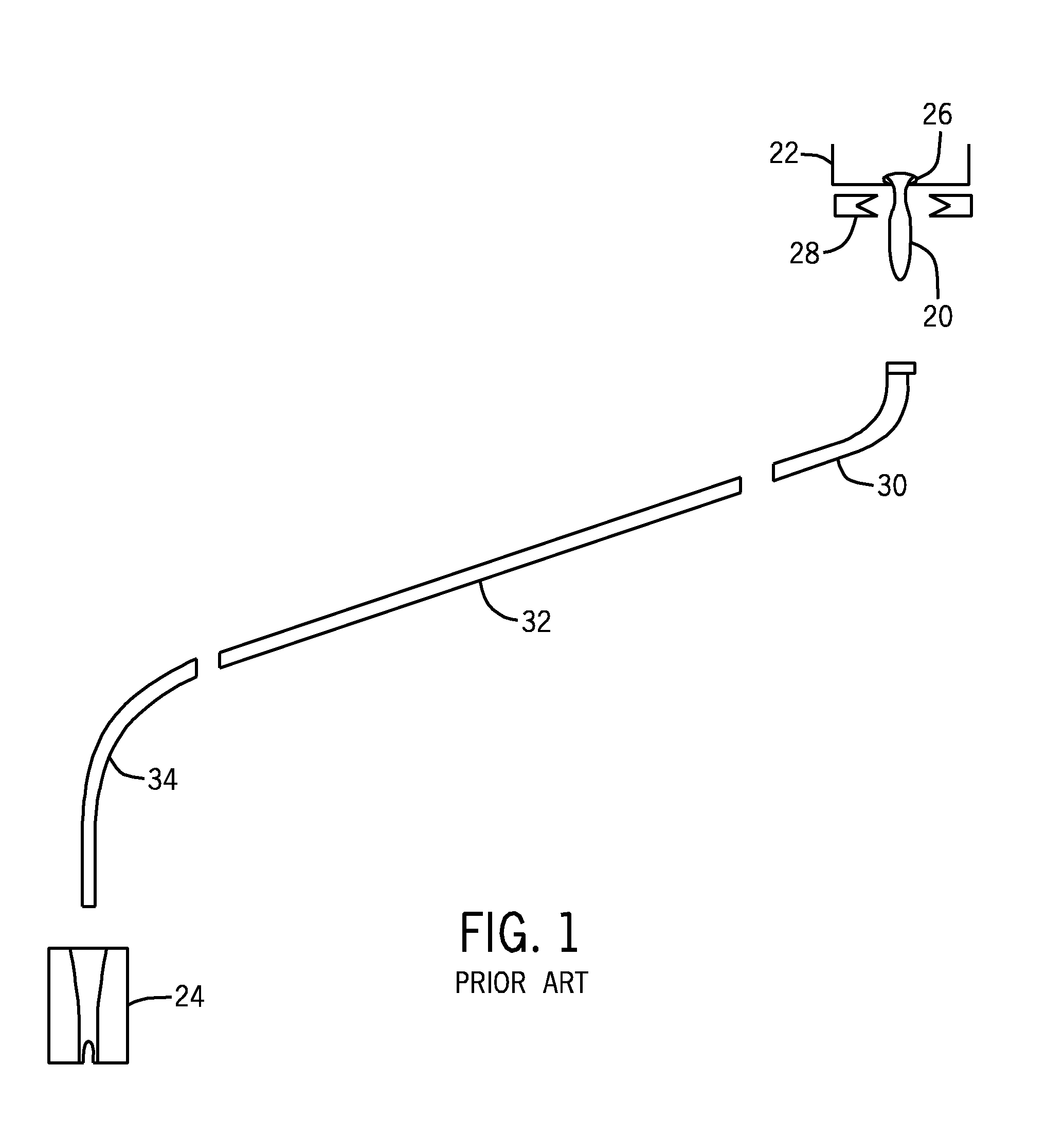
[0033]Prior to discussing the exemplary embodiment of the present invention, it is helpful to briefly describe the location and function of a scoop in a generic glass gob delivery system used to supply glass gobs to an I.S. machine. Referring to FIG. 1, such a glass gob delivery system is illustrated in schematic form depicting the gravitational delivery of a glass gob 20 from a gob feeder 22 to a parison mold 24. Molten glass exits the gob feeder 22 through an orifice 26 in the bottom of the gob feeder 22, and is cut by a schematically depicted glass gob shear mechanism 28 into a sequence of glass gobs 20.

[0034]The glass gobs 20 fall downwardly into the top end of a scoop 30 that is curved to redirect the glass gobs 20 from a vertical trajectory to a diagonal trajectory, and from the bottom end of the scoop 30 into the upper end of an inclined trough 32. From the lower end of the trough 32, the glass gobs 20 are directed into the top end of a deflector 34 that is curved to redirect...


PUM

PropertyMeasurementUnit
acute angleaaaaaaaaaa
diametersaaaaaaaaaa
diametersaaaaaaaaaa

Abstract

An optimized scoop for receiving the glass gobs formed by the shearing mechanism is disclosed which provides an optimal trajectory that enables glass gobs passing therethrough to have an improved glass gob shape together with a negligible increase in glass gob length, with a velocity that is equal to or better than that of previously known scoops. The optimized scoop enhances glass gob shape to produce a more uniformly cylindrical glass gobs and eliminate dog-bone configurations. Trajectory of the optimized scoop is optimized both to enhance exit velocity of the glass gobs and minimize forces applied to the glass gobs.

Description

BACKGROUND OF THE INVENTIONField of the Invention[0001]The present invention relates generally to apparatus for delivering molten gobs of glass supplied by a shearing mechanism from a stream of molten glass to the parison molds of an Individual Section (IS) machine for making glass containers, and more particularly to a scoop for receiving the glass gobs formed by the shearing mechanism and providing an optimal trajectory while ensuring that glass gobs passing therethrough will have an optimal and uniform gob shape.[0002]Glass containers are made in a manufacturing process that has three distinct operations, namely the batch house, the hot end, and the cold end. The batch house is where the raw materials for glass (which are typically sand, soda ash, limestone, feldspar, cullet (crushed, recycled glass), and other raw materials) are prepared and mixed into batches. The hot end melts the batched materials into molten glass, distributes discrete segments of molten glass referred to in...

Claims


Application Information

Patent Timeline
Patent Type & Authority Applications(United States)
IPC IPC(8): C03B17/00C03B7/14
CPCC03B7/16
Inventor MCDERMOTT, BRADEN A.SIMON, JONATHAN S.DING, XU
Owner EMHART GLASS SA
Why Eureka
Try Eureka