Apparatus and method for producing hydrogen-dissolved drinking water

a technology of drinking water and apparatus, which is applied in the direction of membranes, filtration separation, separation processes, etc., can solve the problems of inability to use hydrogen gas cylinders in the home, inability to produce cathode-electrolyzed water as drinking water, and high method cost, and achieve long-term dissolved hydrogen concentration and high dissolved hydrogen concentration

Active Publication Date: 2011-08-18
TECH CORPORATION CO LTD +1
View PDF11 Cites 33 Cited by
  • Summary
  • Abstract
  • Description
  • Claims
  • Application Information

AI Technical Summary

Benefits of technology

[0018]According to the present invention, an apparatus for producing hydrogen-dissolved drinking water that is suitable for drinking, has a high dissolved hydrogen concentration, and has a long dissolved hydrogen concentration life can be provided.

Problems solved by technology

Although the hydrogen gas dissolution method of (1) is simple, a pressure vessel for hazardous substances is required, the method is not easy-to-use, and the method is expensive.
In addition, since hydrogen gas is a hazardous substance, the use of a hydrogen gas cylinder in the home would be difficult.
When the two-chamber electrolytic cell illustrated in FIG. 18 is used, there is an increased chance that the pH will be 8.5 or more if strong electrolysis is carried out, so that the produced cathode-electrolyzed water will not be suitable as drinking water.
Consequently, an effect from the hydrogen molecules cannot be expected.
Thus, the conventional two-chamber electrolytic cell illustrated in FIG. 18 is not suited as a hydrogen-dissolved drinking water production apparatus.
However, because the amount of the cathode-electrolyzed water increases if the flow rate is increased, a larger dissolution efficiency does not always mean that the dissolved hydrogen molecule concentration will increase.

Method used


Image

  • Apparatus and method for producing hydrogen-dissolved drinking water
  • Apparatus and method for producing hydrogen-dissolved drinking water
  • Apparatus and method for producing hydrogen-dissolved drinking water

Examples


example 1

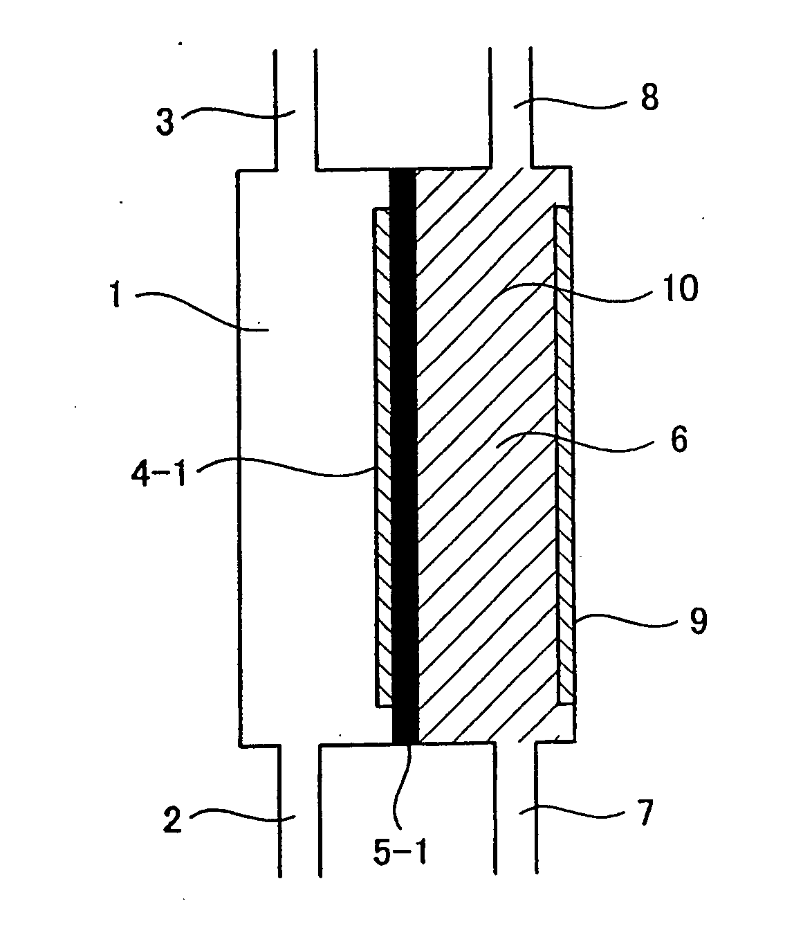
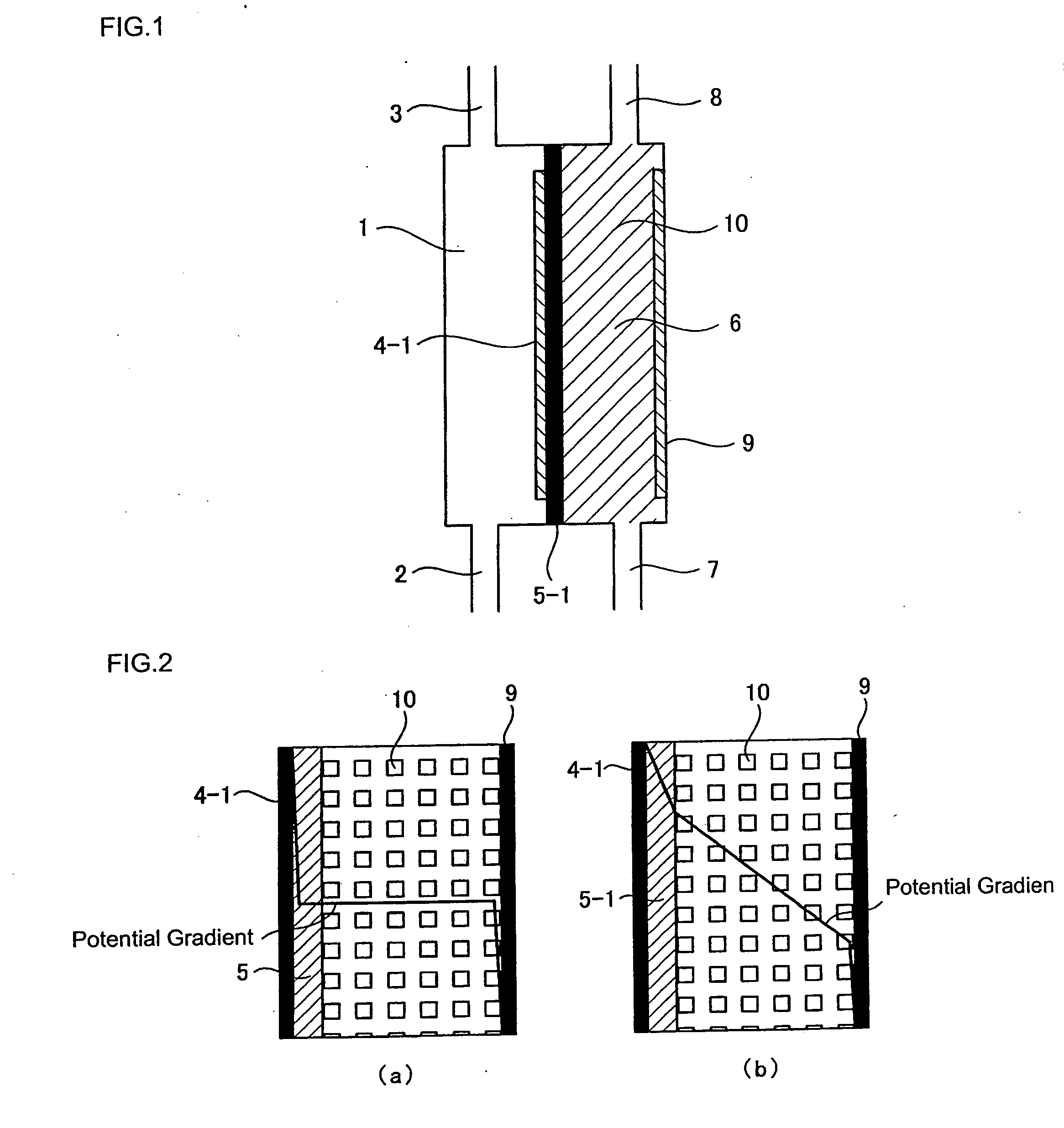
[0104]The relationship among the pH of cathode-electrolyzed water, the structure of the conventional electrolytic cell illustrated in FIG. 19, and the structure of the electrolytic cell according to the present invention illustrated in FIG. 1 was confirmed. The dimensions of the electrodes in the electrolytic cells were 8 cm×6 cm. A fluorine-based cation exchange membrane was used for the diaphragm. A platinum-plated titanium plate was used for the electrodes. However, a water-permeable electrode provided with a plurality of through holes (3 mm φ) as illustrated in FIG. 9 was used for the anode electrode in the electrolytic cell of FIG. 1. In addition, for the electrolytic cell illustrated in FIG. 1, a cation exchange resin 10 was filled between a diaphragm 5-1 formed from a fluorine-based cation exchange membrane manufactured by Dupont and the cathode electrode to a thickness of 5 mm. As the raw water, water obtained by treating tap water using a reverse osmosis membrane filter was...

example 2

[0106]In the electrolytic cell having the structure illustrated in FIG. 1, a water-permeable anode electrode provided with a plurality of through holes (3 mm φ) as illustrated in FIG. 9 and a cathode electrode were used. These electrodes had dimensions of 8 cm×6 cm and an electrode surface area of 48 cm2. The cathode electrode was a flat plate made from platinum-plated titanium that did not have through holes. A fluorine-based cation exchange membrane manufactured by Dupont was used as the diaphragm. A cation exchange resin was filled between the diaphragm and the cathode electrode. The thickness of the ion-exchange resin layer was 5 mm. The cathode-electrolyzed water was passed through a 0.1 micron filter to separate the water into hydrogen molecules in the form of macroscopic gas bubbles (GH) and hydrogen molecules dissolved in particulate form (SH). SH+GH is the total hydrogen amount produced by electrolysis converted from the current. The current was varied between 0.2 and 9.5 A...

example 3

[0108]Using the same electrolytic cell as in Example 2, the flow rate in the cathode electrode chamber and the change in concentration of the dissolved hydrogen molecules were measured. The current was set at 5 A. The water supplied to the cathode electrolysis chamber was pure water of about 1 μS / cm. The effects of flow rate on the ratio (SH / (SH+GH)) between the hydrogen molecule concentration (SH+GH) converted from the current value and the dissolved hydrogen molecule concentration (SH) in the cathode-electrolyzed water passed through a 0.1 micron filter were plotted. The pH of the cathode-electrolyzed water at this time was 6.1 to 6.7. Measurement data concerning the dissolved hydrogen are shown in FIG. 8. From FIG. 8, it can clearly be seen that if the flow rate is increased, the ratio of the dissolved hydrogen concentration increases. However, although the electrolysis voltage was about 9V when the flow rate was 0.1 L / min, the electrolysis voltage was 58V when the flow rate was ...


PUM

PropertyMeasurementUnit
conductivityaaaaaaaaaa
current densityaaaaaaaaaa
pHaaaaaaaaaa

Abstract

An apparatus for producing in the home hydrogen-dissolved drinking water that is suitable for drinking, has a high dissolved hydrogen concentration, and a long dissolved hydrogen life. A hydrogen-dissolved drinking water production apparatus includes an electrolytic cell through which water can pass for producing drinking water having a pH in a range of 2.5 to 8.5, and in particular, in a range of 5.8 to 8.5, and a dissolved hydrogen concentration of 0.1 ppm or more by supplying high-purity water having a conductivity of 50 μS/cm or less. The hydrogen-dissolved drinking water production apparatus is characterized in that the electrolytic cell includes a vertical anode chamber having a water-permeable plate-like anode electrode and a vertical cathode chamber having a plate-like cathode electrode, the anode chamber and the cathode chamber are separated by a diaphragm formed from a fluorine-based cation exchange membrane, the water-permeable plate-like anode electrode is closely adhered to the diaphragm formed from the fluorine-based cation exchange membrane, and an ion-exchange resin is filled in a space between the diaphragm and the cathode electrode.

Description

TECHNICAL FIELD[0001]The present invention relates to an apparatus for producing drinking water in which hydrogen molecules are dissolved (hereinafter, referred to as “hydrogen-dissolved drinking water”), and a method for producing such hydrogen-dissolved drinking water.BACKGROUND ART[0002]The human body utilizes the energy produced when breathed-in oxygen molecules (O2) are reduced to water with a food-derived reducing substance by mitochondria. During this process, some of the oxygen molecules are converted into active oxygen (O2−). Active oxygen is an unstable substance that tends to act as a starting material in the production of hydroxyl radicals (OH.), which tend to be stabilized by taking an electron from the DNA of the human body. Hydroxyl radicals harm DNA, cause arteriosclerosis, contribute to the occurrence of cancer, and are a large factor in lifestyle-related diseases.[0003]Recently, Professor Shigeo Ohta from the Institute of Gerontology, Nippon Medical School, reporte...

Claims


Application Information

Patent Timeline
Patent Type & Authority Applications(United States)
IPC IPC(8): C02F1/461C25B9/10C25B15/08C02F1/44B01D61/02C25B9/19C02F103/04C25B9/23
CPCB01D61/025C25B9/08B01D2311/06C02F1/283C02F1/32C02F1/42C02F1/441C02F1/4676C02F2001/46157C02F2201/46115C02F2201/4618C02F2209/40B01D2311/04Y02E60/366B01D2311/2649B01D2311/2684B01D2311/2626B01D2311/2619Y02E60/36C25B9/19B01D61/02C02F1/44C25B9/00C02F1/46104
Inventor SUMITA, OSAOYIM, SHIN GYO
Owner TECH CORPORATION CO LTD
Why Eureka
Try Eureka