Spiral spring

a spiral spring and spring technology, applied in the field of spiral springs, can solve the problems of spiral springs continuously wound in a distorted condition, spring performance such as correct winding or rewinding cannot be sufficiently exerted, time and skill are required to manufacture spiral springs, etc., to achieve high hardness, avoid abrasion, catching and frictional noise, and reduce metal fatigue

Active Publication Date: 2011-08-18
NIPPON TECH CO LTD
View PDF0 Cites 4 Cited by
  • Summary
  • Abstract
  • Description
  • Claims
  • Application Information

AI Technical Summary

Benefits of technology

[0010]Claim 1 is a spiral spring which is used for a vehicle in which ridges are formed on both ends of the spiral spring in a direction perpendicular to a coiling direction of a surface of a spring plate member so that the ridges project from the surface, projected surfaces of the ridges are curved, and the spring plate member is spirally formed (coiled), wherein
[0011]the spiral spring is formed to have a pitch coiled structure in which an outer spring plate member that is an outer end portion of the spiral, an intermediate spring plate member extending from the outer spring plate member, and an inner spring plate member extending from the intermediate spring plate member are coiled, and
[0012]an engagement piece bent in the radial direction is formed at the end of the outer spring plate member, an engagement coiled core section is formed in the inner spring plate member, and a gap between the intermediate spring plate member and the inner spring plate member is formed to be smaller than a gap between the outer spring plate member and the intermediate spring plate member to form the pitch coiled structure.
[0013]Therefore, claim 1 provides a spiral spring which is a spring plate member formed by a band-like steel plate having high hardness, and in which an engagement piece bent in the radial direction is formed at the end of the outer spring plate member, an engagement coiled core section is formed in the inner spring plate member, a gap between the intermediate spring plate member and the inner spring plate member is formed to be smaller than a gap between the outer spring plate member and the intermediate spring plate member, and a pitch coiled structure best suited to a reclining adjustment mechanism is formed. The invention of claim 1 intends to surely achieve reliable winding of the spiral spring and restoration of the spiral spring to the original state which are characteristics of spiral springs, avoid abrasion, catching, and frictional noise at the time of contact, and reduce metal fatigue.
[0014]Claim 2 is the spiral spring according to claim 1, wherein
[0015]ridges are formed on both ends in a direction perpendicular to the coiling direction of the surface of the spring plate member so that the ridges project from the surface and projected surfaces of the ridges are curved, and material of the spring plate member moves easily to the ridges by forming the center portion of the back surface of the spring plate member to have a concave shape.

Problems solved by technology

However, in a conventional spiral spring, while being wound, there is contact and / or friction and catching between a front surface and a back surface (plate surfaces) facing each other of a spring plate member, and the winding is restricted or stopped at a position where the friction or the catching occurs, or the spiral spring is continuously wound in a distorted condition.
In such a condition, spring performance such as correct winding or rewinding cannot be sufficiently exerted, and problems occur such as, the seat back does not tilt, or the seat back does not return to the original position.
However, this utility model has problems such as, time and skill is required to manufacture the spiral spring, a dedicated machine is required, and the like.
However, this utility model has a structure in which many grooves are formed, so that it cannot be considered to form the spiral spring by cold rolling (material is difficult to move).
In addition, this utility model does not disclose a pitch coiled structure which is best suited to a reclining adjustment mechanism and in which a gap between an outer spring plate member and an intermediate spring plate member and a gap between the intermediate spring plate member and an inner spring plate member are adjusted.
This is a usual spiral spring and it is considered that this spiral spring has a problem when being used as a spiral spring for a vehicle described below.
However, it is considered that the simple structure of this invention in which the inner portion and the outer portion are divided by a line cannot sufficiently cope with a reclining adjustment mechanism in which complex movement of a vehicle and / or an applied load vary.
In particular, the utility models and the inventions in the above-described documents [1] to [6] do not have a means for solving a problem related to the returning speed of the spring and / or the reclining seat, so that it is considered that the utility models and the inventions are not suited to this type of reclining adjustment mechanism.

Method used


Image

  • Spiral spring
  • Spiral spring
  • Spiral spring

Examples


first embodiment

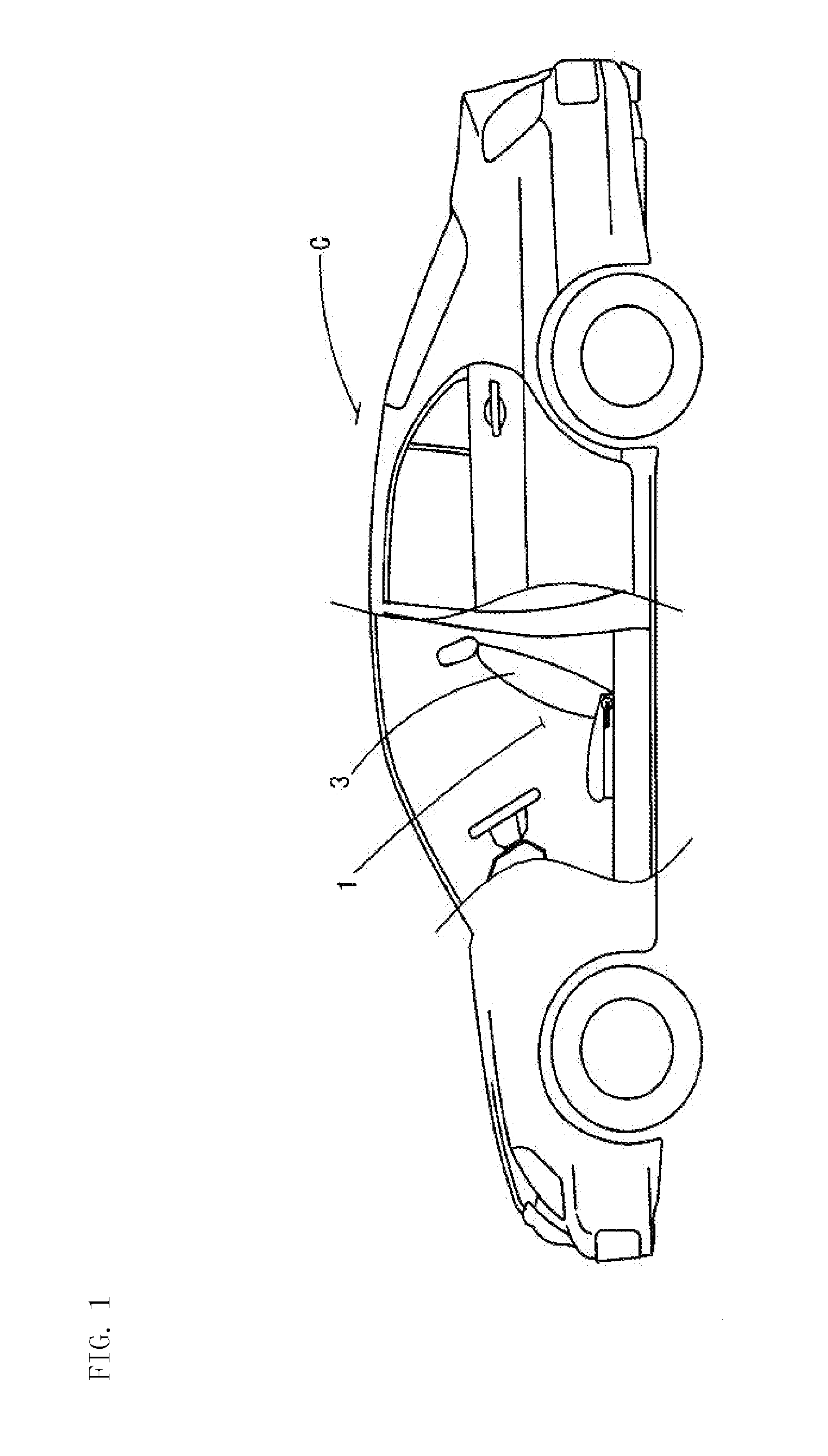
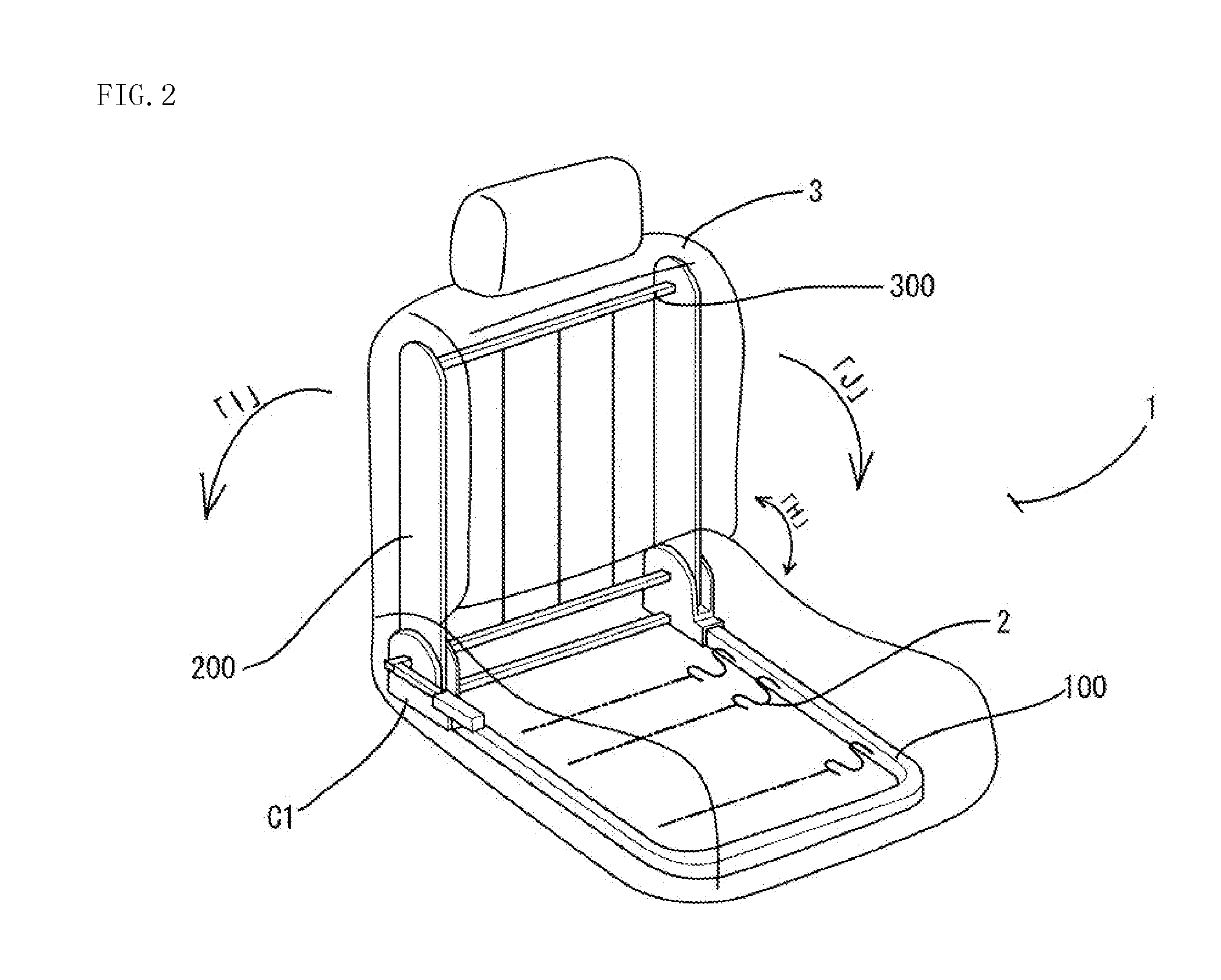
[0045]A first embodiment will be described. Reference numeral 1 in the figures denotes a first seat of a vehicle C. The first seat 1 has a framework including a floor frame 100 attached to a floor and a pair of upper arms 200 attached to the rear end of the floor frame 100. The floor frame 100 is formed into a rectangular frame shape, and a cushion frame 2 including a spring or the like is mounted in the rectangular frame. The cushion frame 2 has a structure covered from the above with a urethane pad (not shown in the figures) and a wool moquette (not shown in the figures). The upper arms 200, 200 (referred to as 200) are respectively attached to the left and the right rear ends of the floor flame 100 (as seen in the driving direction) at the lower end portions of the upper arms 200 so that the upper arms 200 can rotate in the front-back direction (arrow “H”). The upper end portions of the upper arms 200 are linked by a link member 300 having approximately the same length as the lef...

second embodiment

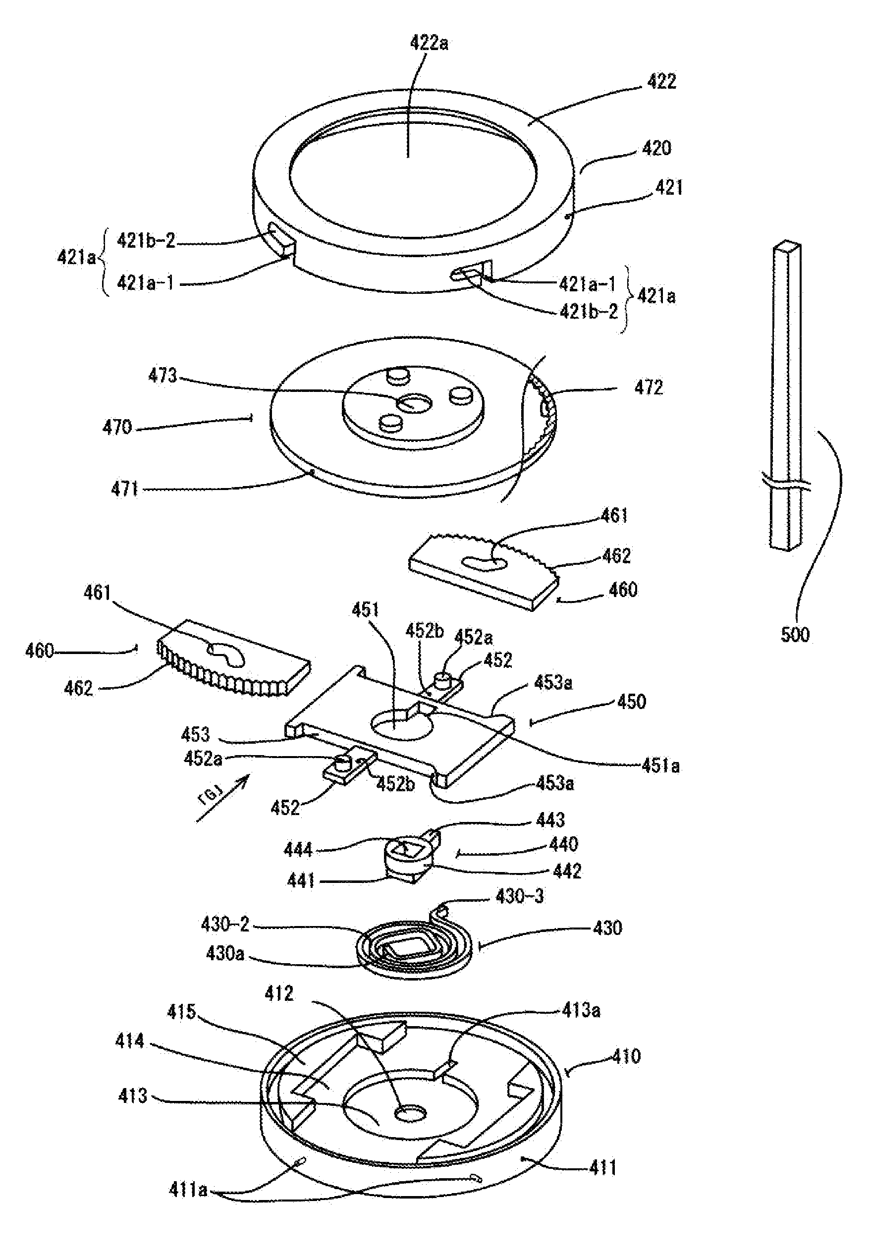
[0056]Next, a second embodiment will be described. FIGS. 12 and 13 show a structure in which the casing 7 is attached (attachably and detachably attached, or integrally attached) to a plurality of engagement band sections D2 (not shown in the figures, but there may be other attaching means) provided on the main body D1 of the lock mechanism D. In the lock mechanism D, the casing 7 includes the side wall 700 and the bottom section 701, and forms a room 702 for containing a spiral spring (described below). In the center of the room 702, the link rod 500 including the engagement groove 710a for engaging an inner spring plate member (described below) of the spiral spring (described below) and the half-cut-ring-shaped movement groove 710 into which the engagement piece 200a projecting from the upper arm 200 located around the link rod 500 are formed. An outer spring plate member (described below) of the spiral spring is engaged with the engagement piece 200a. The spiral spring is engaged...


PUM


Abstract

A spiral spring for a reclining adjustment mechanism for a vehicle seat in which ridges are formed on both ends in a direction perpendicular to a coiling direction of a surface of a spring plate member formed by a band-like steel plate having high hardness so that the ridges project from the surface, projected surfaces of the ridges are curved, and the spring plate member is spirally formed into a coil. The spring plate member has a pitch coiled structure in which a gap between an intermediate spring plate member and an inner spring plate member is formed to be smaller than a gap between an outer spring plate member and the intermediate spring plate member. An engagement piece bent in the radial direction is formed at the end of the outer spring plate member, and an engagement coiled core section is formed in the inner spring plate member.

Description

CROSS REFERENCE TO RELATED APPLICATIONS[0001]This application is a continuation of International Application No. PCT / JP2008 / 67601, filed on Sep. 22, 2008, and designating the United States of America, the entire contents of which is incorporated herein by reference.BACKGROUND OF THE INVENTION[0002]1. Technical Field[0003]The present invention relates to a spiral spring employed in a reclining adjustment mechanism provided in a seat frame of a vehicle, specifically relates to a spiral spring formed by spirally forming (coiling into a pitch coiled structure) a band-like steel plate (spring plate member) having high hardness.[0004]2. Background Art[0005]Conventionally, this type (reclining adjustment mechanism) of spiral spring is wound (tightened) when a seat back is tilted backward, and rewound (loosened) to return to an initial shape when the seat back is tilted forward.[0006]However, in a conventional spiral spring, while being wound, there is contact and / or friction and catching b...

Claims


Application Information

Patent Timeline
Patent Type & Authority Applications(United States)
IPC IPC(8): F16F1/10B60N2/20B60N2/22
CPCF16F1/10B60N2/2356B60N2/236
Inventor YAMADA, NOBUO
Owner NIPPON TECH CO LTD
Why Eureka
Try Eureka