Chair

a technology for chairs and seats, applied in the field of chairs, can solve problems such as damage or damage, and achieve the effects of reducing the number of parts, convenient assembly, and simple structur

Inactive Publication Date: 2011-08-18
OKAMURA CORP
View PDF8 Cites 68 Cited by
  • Summary
  • Abstract
  • Description
  • Claims
  • Application Information

AI Technical Summary

Benefits of technology

[0042]According to the present invention, if the backrest support rod comes in contact with something during turning of the chair, it is securely prevented for the backrest support rod from damaging it or being damaged thereby sl

Problems solved by technology

When the chair turns, the backrest support rod comes in contact wit

Method used


Image

  • Chair
  • Chair
  • Chair

Examples


first embodiment

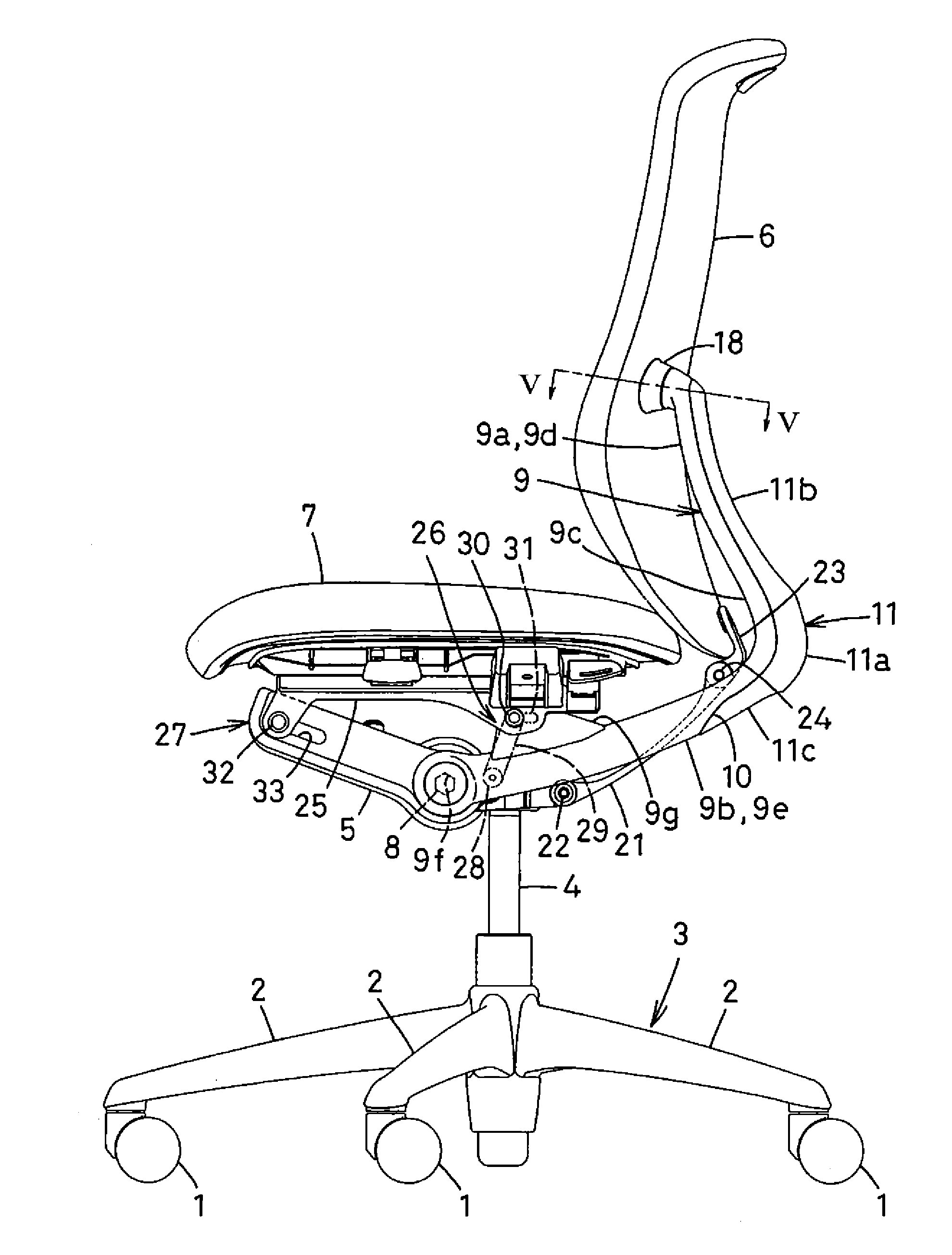
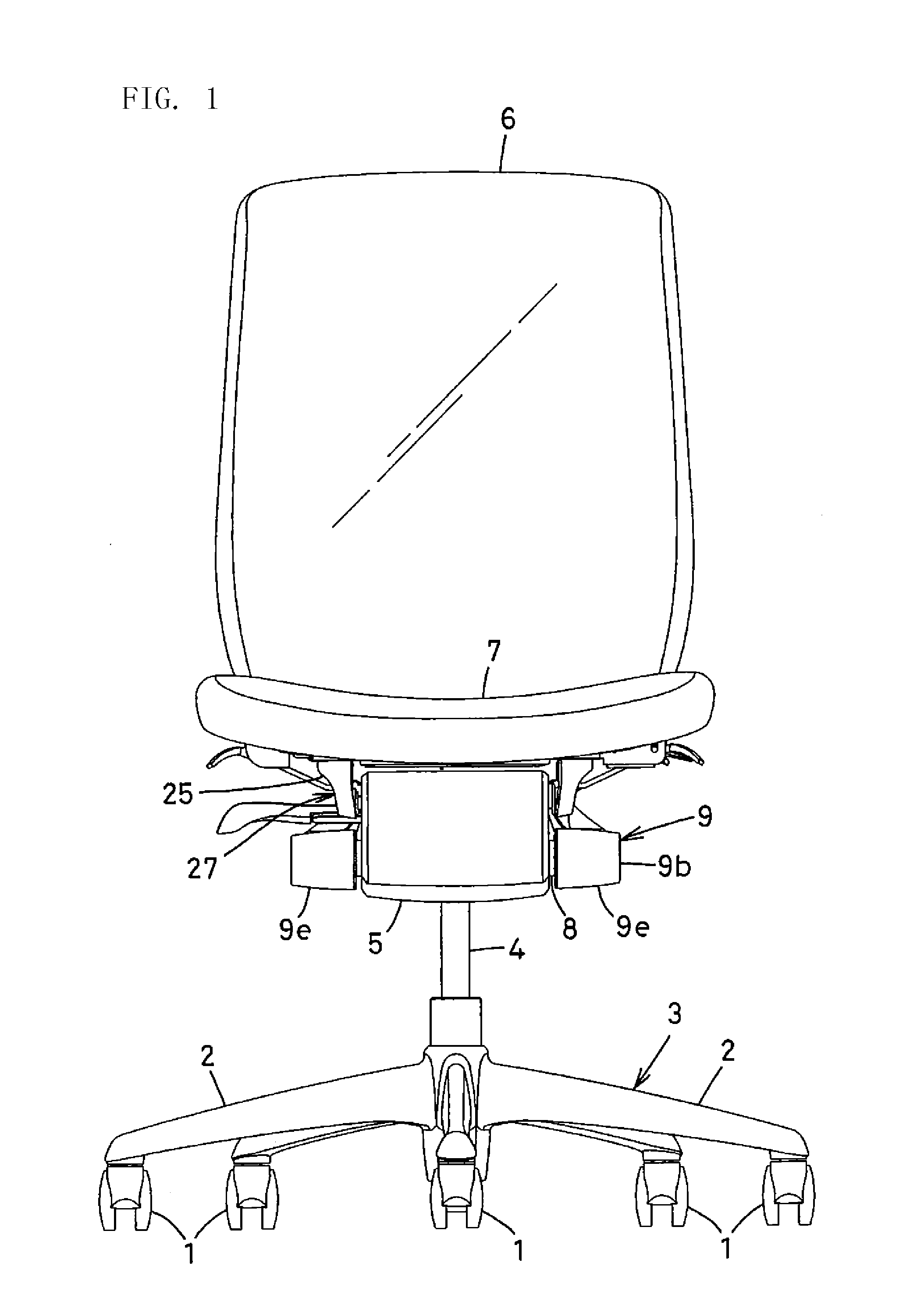
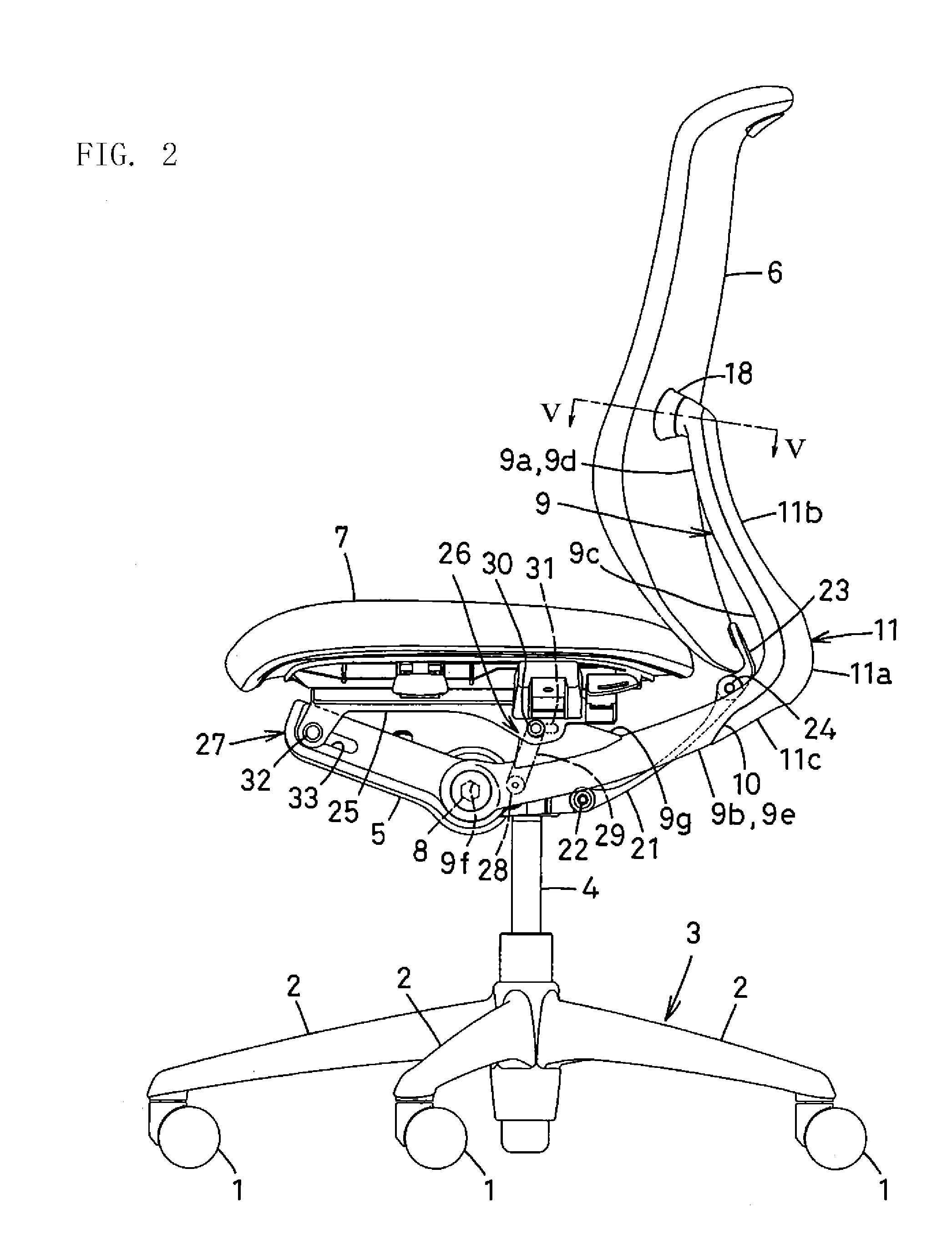
[0062]Embodiments of the present invention will be described with respect to appended drawings. FIGS. 1-6 show a chair according to the present invention.

[0063]As shown in FIGS. 1 and 2, the chair comprises a leg 3 which consists of five leg rods 2 radially disposed. Each of the five leg rods 2 has a caster 1 at the end. In the center of the leg 3, a telescopic leg strut 4 having a gas spring (not shown) stands, and the upper end of the leg strut 4 is fixed to the rear part of a support base 5.

[0064]The support base 5 has an opening at the top and is hollow. The opening is covered with a detachable cover (not shown).

[0065]In the support base 5, there is provided forcing means (not shown) for forcing a backrest 6 to stand up and forcing means (not shown) for forcing a seat 7 forward. But they do not relate to the present invention and are not illustrated or described.

[0066]Through the rear part of the support base 5, a hexagonal pivot shaft 8 is disposed to rotate on its own axis. At...

second embodiment

[0103]FIGS. 7 to 18 shows a chair according to the present invention.

[0104]The same numerals are allotted to the same or similar members as those in the first embodiment and are not described.

[0105]In the first embodiment, the backrest 6 is made of elastically deformable soft synthetic resin or those with cushioning material and skin. In the second embodiment, a backrest 36 comprises a mesh.

[0106]In FIGS. 10-12, the backrest 36 comprises mesh-like stretched material 37 and a backrest frame 39 which covers an opening 38 with the stretched material 37.

[0107]The frame 39 is made of synthetic resin and comprises rectangular main frame 40 comprising a horizontal upper frame 40A, a pair of vertical side frames 40B, 40B that is inclined backward and a horizontal lower frame 40C.

[0108]In FIG. 13, the upper frame 40A of the main frame 40 has an arcuate front surface and a cross section which gets thicker backward. The upper frame 40A has a transverse engagement groove 41 in which an edge 37a...


PUM


Abstract

A chair configured such that a backrest support rod does not make contact with an object when the chair is swiveled and is thus reliably prevented from damaging the object or from being damaged by the object and that the chair uses a reduced number of parts, has a simple structure, and can be easily assembled. A chair, wherein front portions of front facing sections (9b) of a backrest support rod (9) are mounted to a support base (5) supported by a leg body (3) and supporting a seat (7). The backrest support rod (9) is formed in an L-shape in a side view and comprises upwardly facing raised sections (9a) and the forwardly facing front facing sections (9b). The upwardly facing raised sections (9a) and the forwardly facing front facing sections (9b) are connected together through a curved section (9c), and the raised sections (9a) support a backrest (6). A protective cover (11) covers at least that portion of the backrest support rod (9) which extends from the rear surface of the curved section (9c) to the lower surface thereof.

Description

TECHNICAL FIELD[0001]The present invention relates to a chair in which a backrest support rod has an “L” shape.BACKGROUND ART[0002]A conventional chair comprises an “L”-shaped backrest support rod which comprises a vertical portion and a forward portion via a curved portion. When the chair turns, the backrest support rod comes in contact with something and is likely to damage it or be damaged by it slightly. For example, Patent Literature 1 discloses that the back surface and side are covered with soft material.[0003]In Patent Literature 2, connection between a leg frame and a back frame is covered with a connection cover in which two covering portions opens and closes with a hinge.Patent Literature 1: JP2002-136388APatent Literature 2: JP2000-14478ADISCLOSURE OF THE INVENTIONProblems to be Solved by the Invention[0004]However, in Patent Literature 1, the lower surface of the forward portion of the backrest support rod comes in contact with an upper corner of an object on the floor ...

Claims


Application Information

Patent Timeline
IPC IPC(8): A47C3/00
CPCA47C1/03255A47C1/03261A47C7/40A47C1/03294A47C1/03272A47C1/03274A47C7/448A47C7/48
Inventor MASUNAGA, HIROSHIFUJITA, HISATO
Owner OKAMURA CORP
Why Eureka
Try Eureka