Eureka AIR delivers breakthrough ideas for toughest innovation challenges, trusted by R&D personnel around the world.

Current sensor

Active Publication Date: 2011-08-18
DENSO CORP
View PDF9 Cites 11 Cited by
  • Summary
  • Abstract
  • Description
  • Claims
  • Application Information

AI Technical Summary

Benefits of technology

[0010]An embodiment provides a current sensor which is able to measure c

Problems solved by technology

However, measurement of large currents is disabled in this case because the full range is reduced.
However, in this case, the resolution is scaled down and hence the accuracy of measuring very small currents is lowered.
In this way, it has been difficult to measure current in all travel statuses of such a motor vehicle, and to perform accurate control of the vehicle.
More specifically, an attempt to measure a current flow in a parked status using the configuration of measuring the current in an engine start-up status has resulted in insufficient resolution.
Thus, it has been difficult to accurately measure current in a parked status of such a motor vehicle using the configuration for the engine start-up status.
When this type of battery monitor is applied to the measurement of charge / discharge current of an on-vehicle battery, the reliability of the switch will not be ensured because large current flows through the starter in an engine start-up status of the vehicle.
Thus, this type of battery monitor has not been applicable to the measurement of charge / discharge current of an on-vehicle battery.

Method used


Image

  • Current sensor
  • Current sensor
  • Current sensor

Examples


Embodiment Construction

[0020]With reference to the accompanying drawings, hereinafter is described an embodiment of a current sensor.

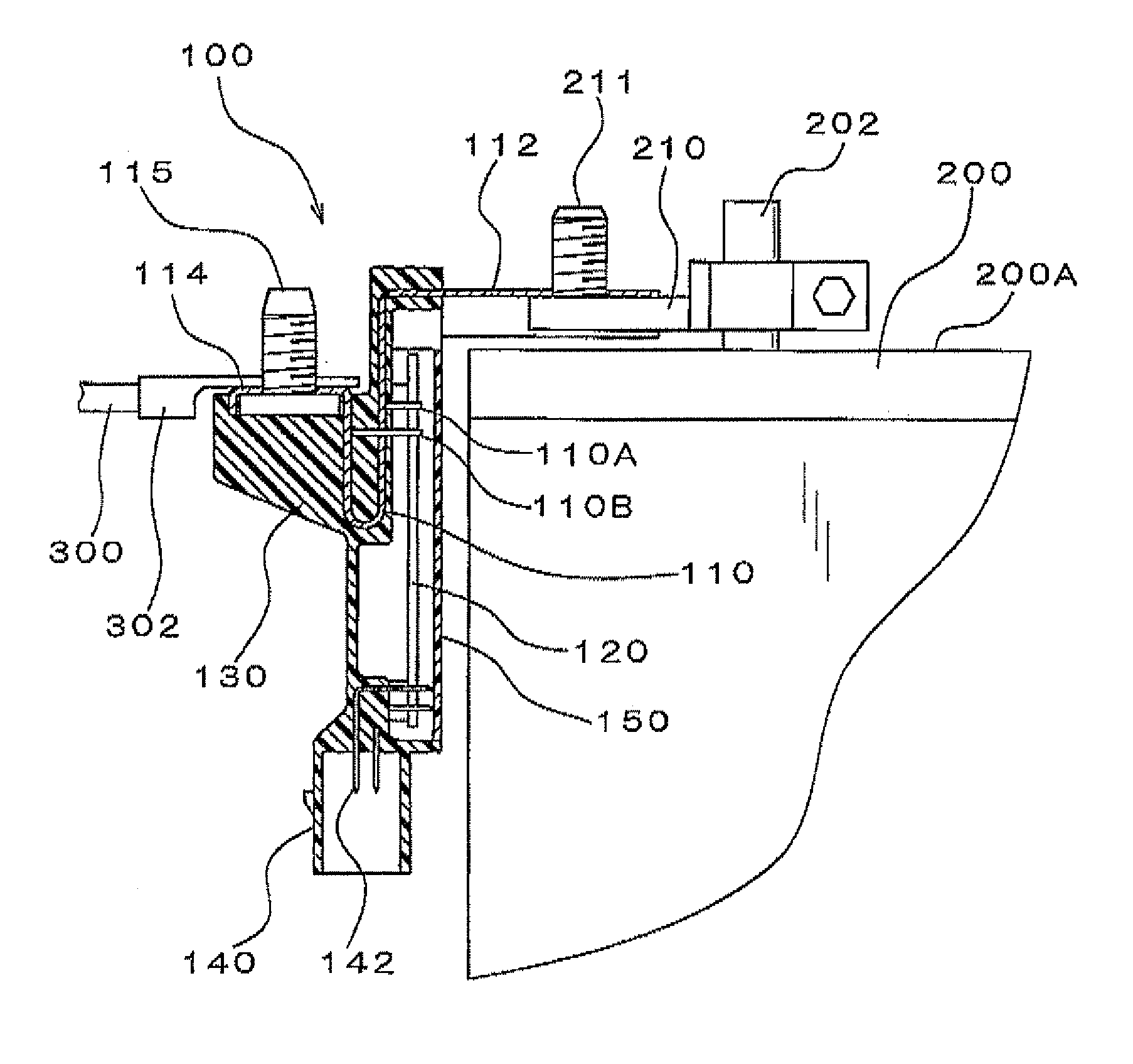
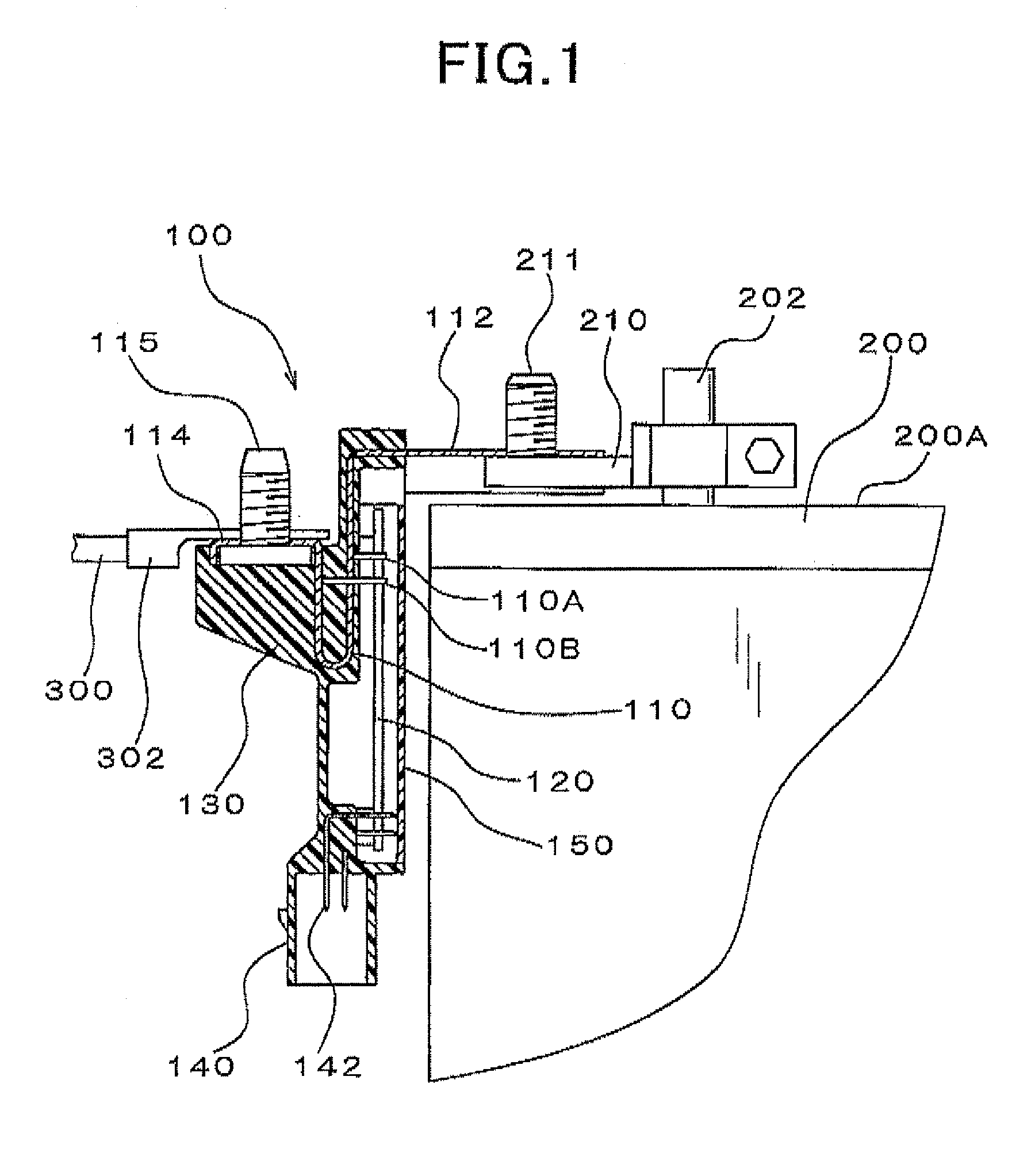
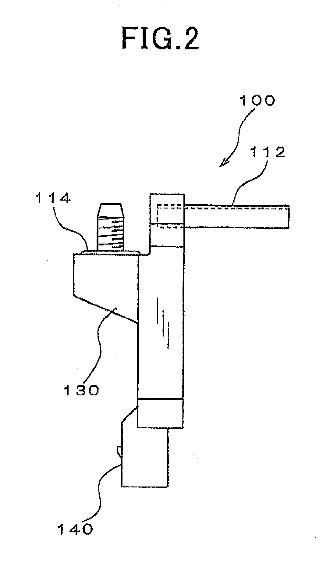
[0021]FIG. 1 is a cross-sectional view illustrating a configuration of a current sensor 100 according to the embodiment. FIG. 1 shows a state where the current sensor 100 is attached to a battery of a motor vehicle. FIG. 2 is a side view illustrating the current sensor 100 and FIG. 3 is a perspective view illustrating the current sensor 100.

[0022]As shown in these figures, the current sensor 100 of the present embodiment includes a bus bar 110, a circuit board 120, a case 130, a connector 140 and a cover 150. The bus bar 110 is made of an electrically conductive material and serves as a resistor (shunt resistor). The circuit board 120 is mounted with a current measuring / processing unit which measures current passing through the bus bar 110 based on a potential difference between two positions along the direction in which current is passed through the bus bar 110. The case 13...


PUM


Abstract

A current sensor, which senses current passing through a harness via a terminal of a battery, includes a fixed part to which the harness is fixed, a resistor which is inserted between the terminal and the fixed part, a circuit board which measures current passing through the resistor based on a potential difference between two positions along the direction in which current is passed through the resistor, and a case which accommodates the resistor and the circuit board. The circuit board includes a plurality of amplifiers which amplify potential difference between the two positions, an analog-digital converter which converts output voltages of the amplifiers into digital data of a predetermined number of bits, and a current measuring / processing unit which measures current passing through the resistor based on the digital data outputted from the analog-digital converter.

Description

CROSS-REFERENCE TO RELATED APPLICATION[0001]This application is based on and claims the benefit of priority from earlier Japanese Patent Application No. 2010-028683 filed Feb. 12, 2010, the description of which is incorporated herein by reference.BACKGROUND[0002]1. Technical Field[0003]The present invention relates to a current sensor that senses charge / discharge current of a battery installed such as in a passenger car or a truck.[0004]2. Related Art[0005]Current sensors have been known. Such known current sensors include battery charge / discharge current sensors as disclosed in JP-A-2009-122056. The battery charge / discharge current sensor disclosed in JP-A-2009-122056 is configured to sense the charge / discharge current of a battery based on voltage across a current sensing resistor inserted between the negative terminal of the battery and a ground. In this battery charge / discharge current sensor, measured currents are summed to calculate the remaining amount of battery, and the cal...

Claims


Application Information

Patent Timeline
IPC IPC(8): G01N27/416H01M50/569
CPCG01R1/203H01M10/48G01R31/3696G01R19/0092G01R31/364Y02E60/10H01M50/569
Inventor TANABE, YASUHITO
Owner DENSO CORP
Why Eureka
Eureka Blog
Learn More