

System for underwater communications comprising fluid modifying means
- Summary
- Abstract
- Description
- Claims
- Application Information
AI Technical Summary
Benefits of technology
Problems solved by technology
Method used
Image

Examples
second embodiment
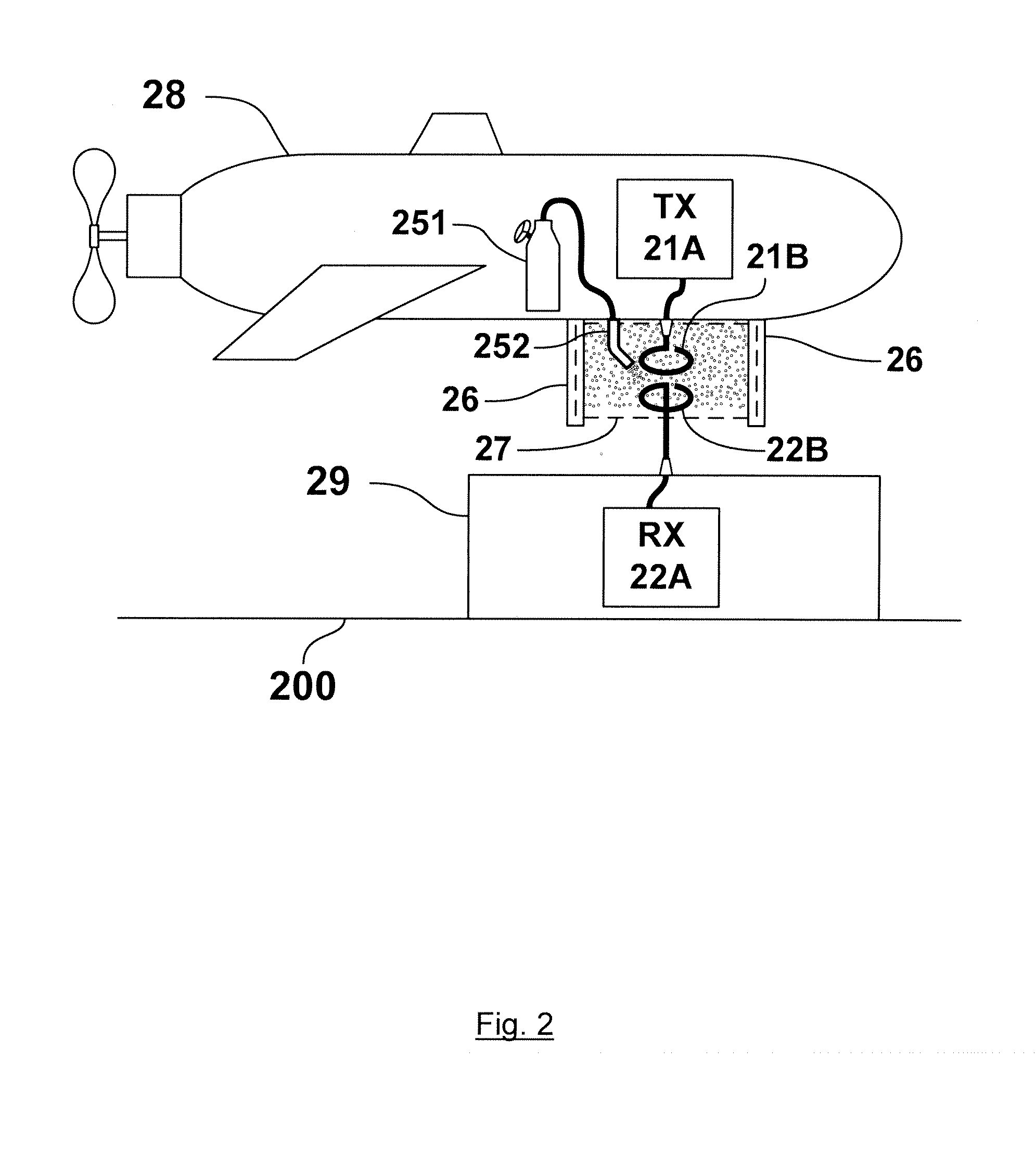
[0043]FIG. 2 shows a diagram of an underwater communications system according to the present invention. The embodiment of the present invention depicted in FIG. 2 comprises transmitter 21A having transmit antenna 21B, receiver 22A having receive antenna 22B, gas supply 251 which is connected to gas jet 252, skirt 26 which defines a volume 27 surrounding TX antenna 21B, underwater vehicle 28 and underwater base station 29. Transmitter 21A is typically housed inside underwater vehicle 28, and is connected to transmit antenna 21B which is mounted on the underside of underwater vehicle 28. Gas supply 251 and gas jet 252 are also housed inside underwater vehicle 28. Receiver 22A is typically housed inside base station 29, and is connected to receive antenna 22B which is mounted on an upper surface of base station 29. Base station 29 is typically located on the seabed 200. In use, underwater vehicle 28 navigates to a location so that transmit antenna 21B and receive antenna 22B are locate...
third embodiment
[0048]FIG. 5 shows a diagram of an underwater communications system according to the present invention. The embodiment of the present invention depicted in FIG. 5 comprises transmitter 51A having transmit antenna 51B, receiver 52A having receive antenna 52B, electrodes 55A, 55B, underwater vehicle 58 and underwater base station 59. Transmitter 51A is typically housed inside underwater vehicle 58, and is connected to transmit antenna 51B which is mounted on the underside of underwater vehicle 58. Receiver 52A is typically housed inside base station 59, and is connected to receive antenna 52B which is mounted on an upper surface of base station 59, similarly electrodes 55A, 55B are mounted on the same upper surface of base station 59, so that receive antenna 52B is sandwiched between electrodes 55A, 55B. In use, underwater vehicle 58 navigates to a location so that transmit antenna 51B and receive antenna 52B are located within a short distance of each other and so that transmit anten...
fourth embodiment
[0050]FIG. 6 shows a diagram of an underwater communications system according to the present invention. The embodiment of the present invention depicted in FIG. 6 comprises transmitter 61A having transmit antenna 61B, receiver 62A having receive antenna 62B, liquid outlet 65, skirt 66 defining a volume 67, underwater vehicle 68 and underwater base station 69. Transmitter 61A is housed inside underwater vehicle 68 and is connected to transmit antenna 61B which is mounted on the underside of underwater vehicle 68. Receiver 62A is housed inside base station 69 and is connected to receive antenna 62B which is housed on an upper surface of base station 69. Skirt 66 is attached to the underside of underwater vehicle 68 and surrounds transmit antenna 61B. In use, underwater vehicle 68 navigates so that transmit antenna 61B and receive antenna 62B are located adjacent to each other. The preferred position of underwater vehicle 68 is so that both transmit antenna 61B and receive antenna 62B ...
PUM
 Abstract
Description
Claims
Application Information