Cutting device for shear-cutting of fibre strands

a cutting device and cutting technology, applied in the direction of feeding apparatus, automatic control device, shearing apparatus, etc., can solve the problem of unsatisfactory cut quality of fine endless fibres to be cut, and achieve the effect of high fibre strand throughput and high cut quality

Inactive Publication Date: 2011-08-25
SCHMIDT & HEINZMANN
View PDF23 Cites 7 Cited by
  • Summary
  • Abstract
  • Description
  • Claims
  • Application Information

AI Technical Summary

Benefits of technology

[0005]It is the object of the invention to provide a cutting device for fibre strands which

Problems solved by technology

The drawback of this cutting device is that the cut quali

Method used


Image

  • Cutting device for shear-cutting of fibre strands
  • Cutting device for shear-cutting of fibre strands
  • Cutting device for shear-cutting of fibre strands

Examples


Embodiment Construction

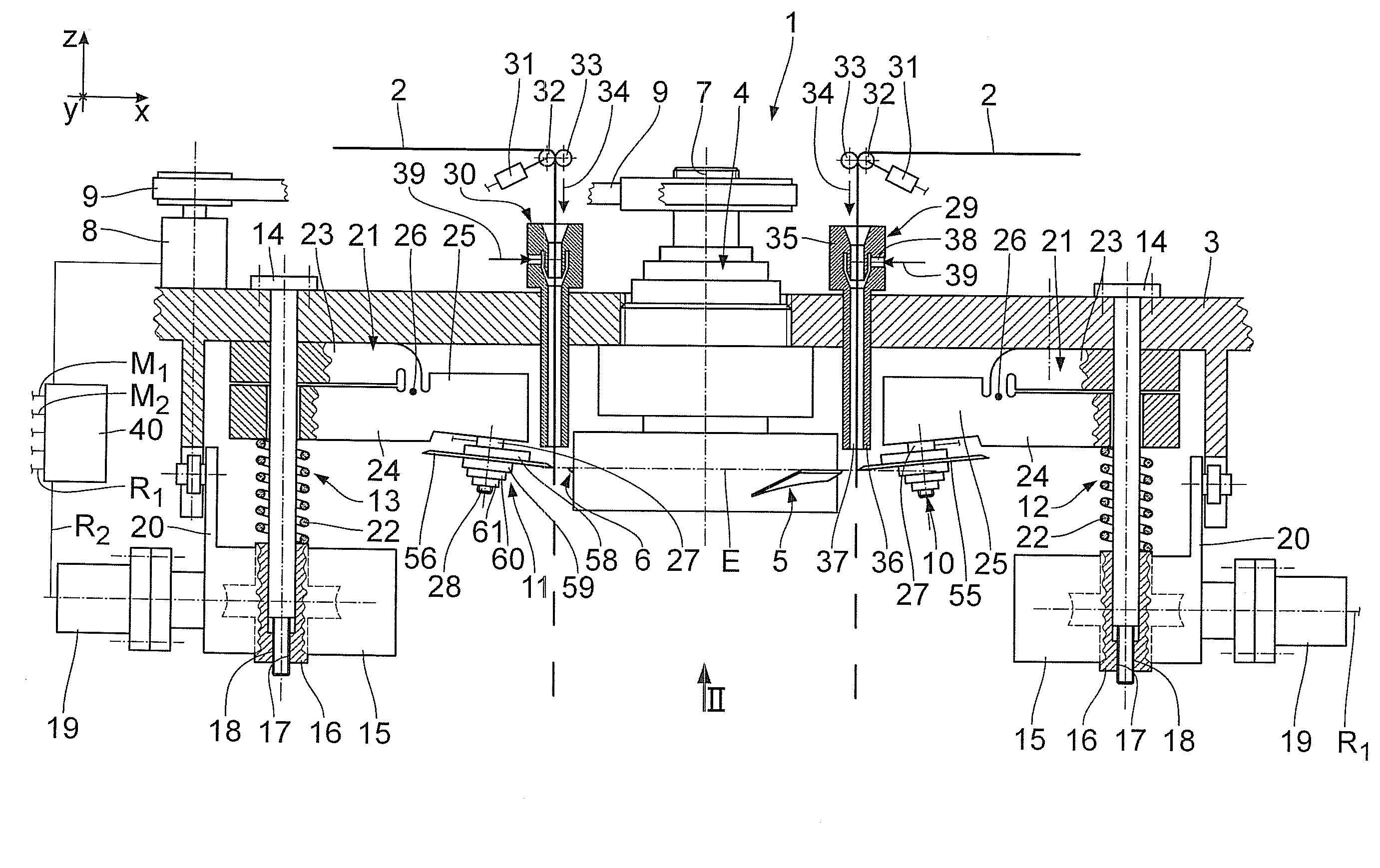
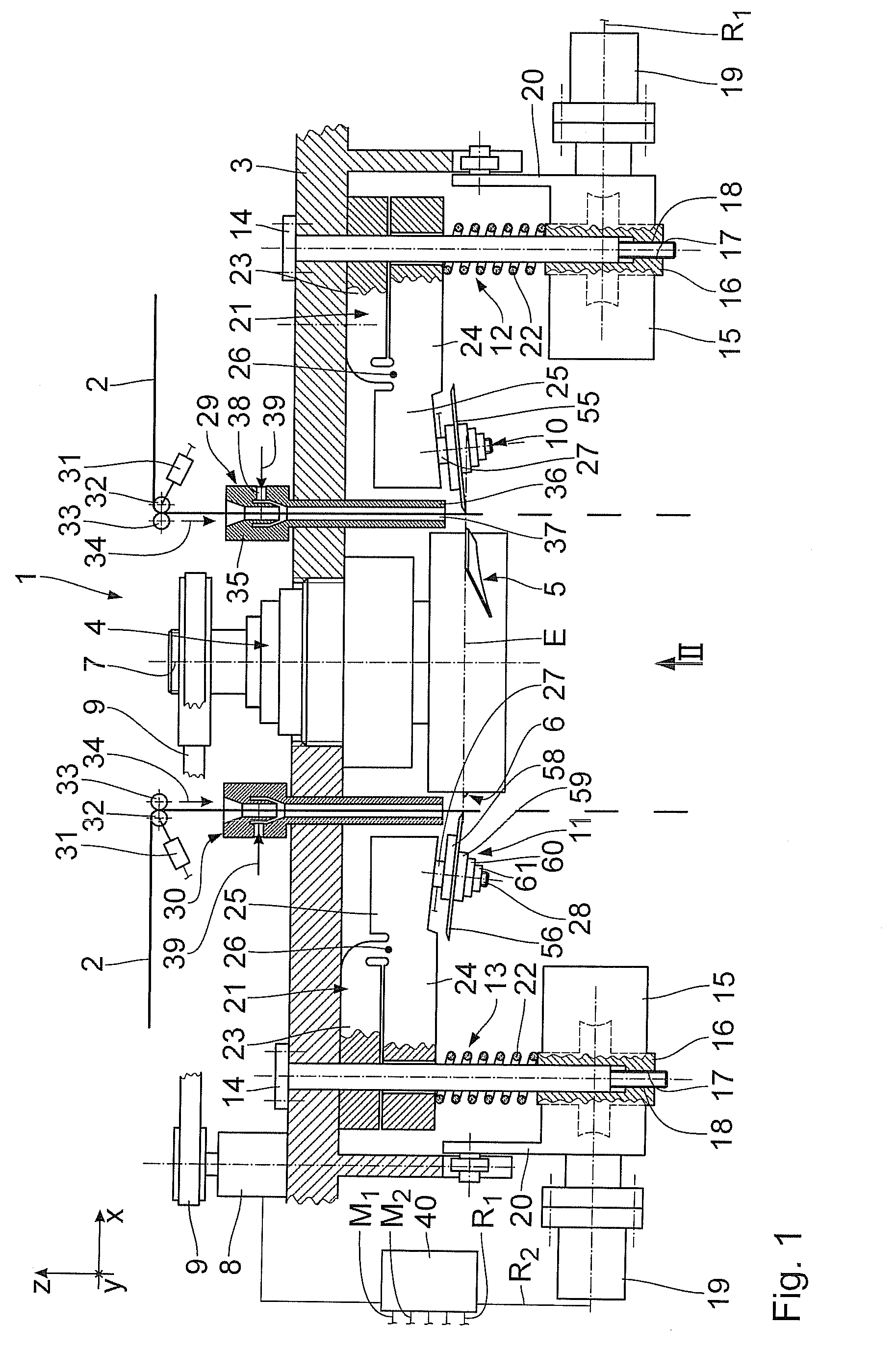
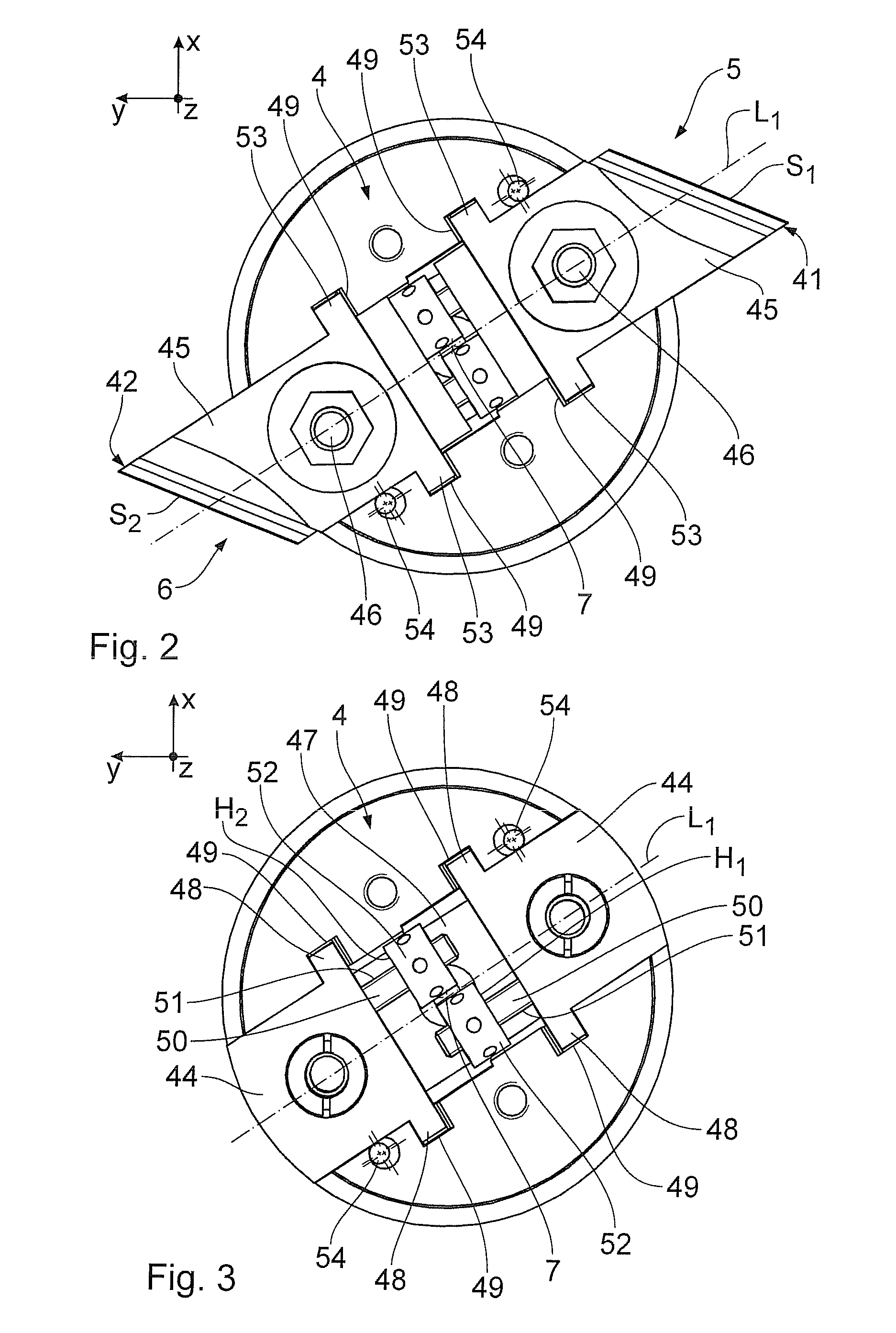
[0028]A cutting device for shear-cutting of endless fibre strands 2 comprises a base frame 3 on which a cutting spindle 4 comprising two cutting units 5 and 6 is arranged. The cutting spindle 4 has an axis of rotation 7 which is parallel to a vertical z-direction. By means of a spindle drive 8, the cutting spindle 4 is rotatably drivable about the axis of rotation 7 via a belt drive 9. The cutting units 5 and 6 are arranged in a rotationally symmetric manner about the axis of rotation 7 at an angle of rotation of 180°. The cutting units 5 and 6 may principally be arranged in a rotationally symmetric manner about the axis of rotation at any desired angle of rotation, for example at an angle of rotation of 120° or 90° . The cutting units 5 and 6 are only outlined in FIG. 1 and will be described in more detail below.

[0029]For shear-cutting the fibre strands 2, the cutting device 1 comprises two counter cutting units 10 and 11 which are arranged at associated electrically driven displac...


PUM

PropertyMeasurementUnit
Forceaaaaaaaaaa
Angleaaaaaaaaaa
Piezoelectricityaaaaaaaaaa

Abstract

A cutting device for shear-cutting of fibre strands comprises at least two cutting units which are rotatably drivable about an axis of rotation and two counter cutting units which are rigidly mounted relative to a base frame. The cutting edges of the cutting units as well as the counter cutting edges of the counter cutting units are positionable relative to a common cutting plane independently of each other. The forces acting on the counter cutting edges are measured during a cutting process by means of corresponding measuring sensors, allowing the position of the counter cutting edges to be controlled by means of a control unit via electrically driven displacement devices.

Description

BACKGROUND OF THE INVENTION[0001]1. Field of the Invention[0002]The invention relates to a cutting device for shear-cutting of fibre strands.[0003]2. Background Art[0004]DE 10 2007 052 586 A1 discloses a cutting device which cuts endless fibres into staple fibres. The cutting device comprises two blades mounted to a rotating cutting spindle which are coupled to each other via a positive fit coupling and alternately act as compensation weights for compensating the centrifugal forces occurring during operation. The cutting units are assigned to two cutting units which are rigidly arranged on a base frame, thus causing the endless fibres disposed between the cutting units to be cut into pieces when the cutting spindle is rotating. The number of cutting units allows a high throughput to be achieved. The drawback of this cutting device is that the cut quality of the fine endless fibres to be cut is unsatisfactory.SUMMARY OF THE INVENTION[0005]It is the object of the invention to provide ...

Claims


Application Information

Patent Timeline
IPC IPC(8): B26D5/02
CPCD01G1/10D01G1/04Y10T83/148Y10T83/7847
Inventor BRUSSEL, RICHARD
Owner SCHMIDT & HEINZMANN
Why Eureka
Try Eureka